Quantcast
Channel: sensor | Battery Guide
Viewing all 406 articles
Browse latest View live

HDC1050 Low Power, High Accuracy Digital Humidity Sensor with Temperature Sensor (Rev. C)

$
0
0

1 Features

  • Relative Humidity Accuracy ±3% (typical)
  • Temperature Accuracy ±0.2°C (typical)
  • 14 Bit Measurement Resolution
  • 100 nA Sleep Mode Current
  • Average Supply Current:
    • 710 nA @ 1sps, 11 bit RH Measurement
    • 1.3 µA @ 1sps, 11 bit RH and Temperature Measurement
  • Supply Voltage 2.7 V to 5.5 V
  • Small 3 mm x 3 mm Device Footprint
  • I2C Interface
    HDC1050 Low Power, High Accuracy Digital Humidity Sensor with Temperature Sensor

2 Applications

  • HVAC
  • Smart Thermostats and Room Monitors
  • White Goods
  • Printers
  • Handheld Meters
  • Medical Devices
  • Wireless Sensor (TIDA-00374)

3 Description

The HDC1050 is a digital humidity sensor with integrated temperature sensor that provides excellent measurement accuracy at very low power. The HDC1050 operates over a wide supply range, and is a low cost, low power alternative to competitive solutions in a wide range of common applications. The humidity and temperature sensors are factory calibrated.

Device Information (1)

PART NUMBER PACKAGE BODY SIZE (NOM)
HDC1050 PWSON (6-pin) DMB 3.00 mm x 3.00 mm
  1. For all available packages, see the orderable addendum at the end of the datasheet.

4 Typical Application

Copyright© 2015, Texas Instruments Incorporated. An IMPORTANT NOTICE at the end of this data sheet addresses availability, warranty, changes, use in safety-critical applications, intellectual property matters and other important disclaimers.

Submit Documentation Feedback

For more detail:  HDC1050 Low Power, High Accuracy Digital Humidity Sensor with Temperature Sensor (Rev. C)

The post HDC1050 Low Power, High Accuracy Digital Humidity Sensor with Temperature Sensor (Rev. C) appeared first on PIC Microcontroller.


4 DIGITS THERMOMETER USING DS18B20 DIGITAL SENSOR

$
0
0

Updated on 17/01/2016 (a and b segments were swapped on drawing)
Counter based on PIC16F628A . Included C code and circuit diagram. Displays -55 to 125 centigrade.
The temperature is read every 15 seconds, can be changed in the code. The math is using integers to calculate the degrees and the tenths of degrees are calculated separately.

4 DIGITS THERMOMETER USING DS18B20 DIGITAL SENSOR
The 7 segment LED is common cathode, 4 separate digits can be used with segments a to g linked.

You are free to use the circuit diagram and the software with no limitations.All transistors are BC337 or equivalent.
Total 5V supply current is 90mA.
The 4 digits display is common cathode, the 7 resistors of 220 ohms enable current of 15 mA for each segment which is on for 25% of the time. The seven segments, a to g, of one digit are linked to the corresponding seven segments in the other digits.
Segment e is connected differently because RA4 is an open drain output.
The 4 digits are multiplexed by pins 6-9 that drive the common cathodes cc1-cc4.
DP is the decimal point.
DS18B20 can be any type.

For more detail:    4 DIGITS THERMOMETER USING DS18B20 DIGITAL SENSOR

The post 4 DIGITS THERMOMETER USING DS18B20 DIGITAL SENSOR appeared first on PIC Microcontroller.

LED fireflies prototype using PIC12f683 microcontroller

$
0
0

LED fireflies prototype

hello all, heres an attempt i made at something like an LED throwie..the problem (for me) with led throwies is that they just consume their battery, and produce light.. but they could be better at doing both..
LED fireflies

first you have to accept the premise that your willing to spend a bit more for the tradeoff..

the inspiration for this came from some of my other projects, and of course the “LED as a sensor” concept as well as the “LED throwie”

so the parts list:
1 common cathode, tri-color (RGB) LED
1 12f683 pic micro
1 coin cell battery holder

(cheap plug) http://www.makenyc.org/

Step 1: So whats it do?

the idea here is to use the led throwie/graffiti concept, to add a little life to my neighborhood that ive been missing for a long time now… fireflies..

the software is designed to use the LED as a light sensor (so as not to waste power during the day)

the led as an entropy source (to make each firefly unique moments after switching it on) to vary blink color, and rate.

and of course to play a flash pattern every so often in a way that seems “organic” and isnt just an “on/off” blink

and of course use as little power as possible!

(apologies for the darkness of the video, but the light had to be dim enough not to trip the fireflies daylight sensor)

For more detail: LED fireflies prototype using PIC12f683 microcontroller

The post LED fireflies prototype using PIC12f683 microcontroller appeared first on PIC Microcontroller.

Interface single and Dual IR Infrared sensor with PIC18F4550 and LCD

$
0
0

In this another tutorial on sensors  for beginners, we are going to interface single and multiple Infrared IR sensors with Arduino Uno development board, working simultaneously and have the status displayed either on an ( 4X16 LCD ) LCD module (jhd162a) or an LED. We are going to cover three chapters in single tutorial in simple step by step fashion. The purpose of this tutorial is to serve the basics for beginners with Sensor interface on Arduino for being able to use these concepts and to develop various other sensor based applications (robotics, Automation Projects etc.). We will use the same Object Detection Proximity IR Sensor Module that we made in our precedent tutorial. In our previous Proximity Sensor tutorials we have learned how to interface IR sensor with various other microcontrollers such as PIC18F4550 and 18F2550; However, today we are going to learn how to interface the same infrared sensor with the famous Arduino Uno board.Interface single and Dual IR Infrared sensor with Arduino and LCD

To begin easy, first we are going to interface a Single IR sensor for sensing the distance and read the value of the sensor using an Arduino board and have status displayed on a LED. On the next level we are going to do same with two IR sensors working simultaneously. At last we will interface (add) an LCD (Liquid Crystal Display) and have the status of both the Infrared sensors displayed on a 4X16 LCD Display unit. The Concepts for Reading the IR sensor is still same as explained in previous lessons, the only difference is the Arduino board.

Tutorials

Requirements

PIC18F4550
– Infrared IR sensor Module
– JHD162a 4X16 LCD
– Resistors
– LEDS

Infrared IR Sensor Module

We will use the IR Infrared Sensor Circuit module that we made in our previous project, which is an inexpensive (Low Cost)  sensor circuit module. You can find the schematic and PCB design in my previous post. There are three pins in the Schematic – Two pins for providing the input voltage and GND, and the third pin from the IR module is the IR control pin. This Control Pin from the IR sensor Module will be interfaced to the Arduino for reading the value from sensor. We will use two identical copies of the sensor for our tutorial.

Single Infrared IR Sensor Interface to PIC18F4550Microcontroller

Chapter1

As mentioned before we are going to start easy,hence here we going to interface just one infrared sensor circuit with Arduino, the source code is pretty much self-explanatory. Like every microcontroller, we need to define pins either as input or output. We have configured Pin 13 as output, and pin 9 as input for taking input from sensor. The Result of sensor will reflect on the LED connected on pin13 which is configured as output. The source code can be tweaked easily to display the result on serial monitor too.

We are going to leave pin 0 to Pin 7 on Arduino Uno untouched for using it with LCD operation in future. Make the Circuit ready according to the schematics below to proceed further. Arduino will draw power from USB hence there is no need to interface external power supply as long as the board is connected with USB cable.Interface single and Dual IR Infrared sensor with Arduino and LCD schematich

Schematic (Single Sensor Interface)

USE and GND and +5V pins on the arduino to power the IR sensors. Make the necessary wiring acording to the schamatic given below.

NOTE: The operation is quiet similar to that of interfacing a simple switch to Arduino or any microcontroller, But here you don’t need to ground the input pin (pull-down) with a resister. In Arduino pin13 by default is interfaced with an Onboard led for displaying status. We can use that one onboard led or you can interface an Extra led on Pin 13 to have the Status displayed.


For more detail: Interface single and Dual IR Infrared sensor with PIC18F4550 and LCD

The post Interface single and Dual IR Infrared sensor with PIC18F4550 and LCD appeared first on PIC Microcontroller.

Humidity and temperature measurements with Sensirion’s SHT1x/SHT7x sensors using PIC18F2550 (Part 1)

$
0
0

Temperature and relative humidity are two very important ambient parameters that are directly related to human comfort. Sometimes, you may be able to bear higher temperatures, if there is a lower relative humidity, such as in hot and dry desert-like environment. However, being in a humid place with not very high temperature may make you feel like melting. This is because if there is high relative humidity, sweat from our body will evaporate less into the air and we feel much hotter than the actual temperature. Humidifiers and dehumidifiers help to keep indoor humidity at a comfortable level. Today we will discuss about Sensirion’s SHT series of digital sensors, more specifically SHT11 and SHT75, which are capable of measuring both temperature and relative humidity and provide fully calibrated digital outputs. We will interface both the sensors to PIC18F2550 microcontroller and compare the two sets of  measurements to see the consistency between the two sensors. This tutorial is divided into two parts. The first part will cover all the details regarding the sensors, including their specification, interface, and communication protocol. The second part will be more focussed on the circuit diagram, implementation of the communication protocol with PICMicro, and the results.

Sensirion’s SHT1x

Theory

Sensirion offers multiple SHT series of digital sensors for measuring both relative humidity and temperature. The temperature is measured using a band-gap sensor, whereas the humidity sensor is capacitive; which means the presence of moisture in air changes the dielectric constant of the material in between the two plates of a parallel-plate capacitor, and hence varies the capacitance. The required signal conditioning, analog-to-digital conversion, and digital interface circuitries are all integrated onto the sensor chip. The various SHT series sensors have different levels of accuracy for humidity and temperature measurements, as described below.

SHT1x, 2x, and 7x series of humidity sensors (Source: http://www.sensirion.com)

SHT1x are available in surface mount type whereas SHT7x are supplied with four pins which allows easy connection. The SHT11 and SHT75 sensors both provide fully calibrated digital outputs that can be read through a two-wire (SDA for data and SCK for clock) serial interface which looks like I2C but actually it is not compatible with I2C. An external pull-up resistor is required to pull the signal high on the SDA line. However, the SCK line could be driven without any pull-up resistor. The signaling detail of the serial bus is described in the datasheet, which we will implement for PIC18F2550 microcontroller using mikroC pro for PIC compiler. The operating range of both the sensors is 0 to 100% for relative humidity, and -40.0 to 123.8 °C for temperature. The sensor consumes 3 mW power during measurement, and 5 μW, while in sleep mode.

The SHT11 module that I have got is from mikroElektronika. The sensor (SMD) is soldered on a tiny proto board with all the four pins accessible through a standard 0.1 inch spacing male header. The board comes with pull-up resistors connected to both SDA and SCK lines. One concern in this type of arrangement is the heat dissipated by the pull-up resistors could affect the measurements if the resistors and the sensor are close in the board. We will discuss about this issue later too. The SHT75 module from Sensirion, however, does not include any pull-up resistor for SDA line and therefore must be included externally.


For more detial: Humidity and temperature measurements with Sensirion’s SHT1x/SHT7x sensors using PIC18F2550 (Part 1)

Current Project / Post can also be found using:

  • transducers based projects

The post Humidity and temperature measurements with Sensirion’s SHT1x/SHT7x sensors using PIC18F2550 (Part 1) appeared first on PIC Microcontroller.

The world’s tiniest temperature sensor is powered by radio waves

$
0
0

Researchers at TU/e have developed a very tiny wireless temperature sensor that is powered in a very special way: from the radio waves that are part of the sensor’s wireless network. This means that the sensor needs not even a single wire, nor a battery that would have to be replaced. The arrival of such sensors is an important development on route towards smart buildings, for instance. But the applications are many and various.

2013_0117_BC

The smart buildings of the future will be full of sensors that will respond to the residents’ every need, and will be as sustainable as possible. Like heating and lighting that only switches on when someone is in the room. That’s only possible if these sensors are wireless and need no batteries, otherwise in a large building you would have to change the batteries every day. This is  demonstrated by TU/e researcher Hao Gao who will be awarded his PhD on Monday 7 December for his thesis in which he developed a sensor that measures just 2 square millimeters and weights a mere 1.6 milligrams, equivalent to a grain of sand.

The current version of the sensor has a range of 2.5 centimeters; the researchers expect to extend this to a meter within a year, and ultimately to 5 meters. The sensor has a specially developed router, with an antenna that sends radio waves to the sensors to power them. Since this energy transfer is accurately targeted at the sensor, the router consumes very little electricity. And the sensors themselves are made such that their energy consumption is extremely low. The sensor also operates beneath a layer of paint, plaster or concrete. As Peter Baltus, TU/e professor of wireless technology, explains, this makes the sensor easy to incorporate in buildings, for instance by ‘painting’ it onto the wall with the latex.

The sensor contains an antenna that captures the energy from the router. The sensor stores that energy and, once there is enough, the sensor switches on, measures the temperature and sends a signal to the router. This signal has a slightly distinctive frequency, depending on the temperature measured. The router can deduce the temperature from this distinctive frequency.

The same technology enables other wireless sensors to be made, for example to measure movement, light and humidity. The application areas are enormous, Baltus says, ranging from payment systems and wireless identification to smart buildings and industrial production systems. They won’t be expensive either: mass production will keep the cost of a sensor down to around 20 cents. The sensor is based on 65-nm CMOS technology.

For more detail:  The world’s tiniest temperature sensor is powered by radio waves

The post The world’s tiniest temperature sensor is powered by radio waves appeared first on PIC Microcontroller.

MCU controlled Bluetooth automation with infrared sensor

$
0
0

The microcontroller used is 0822 zilog encore! 8k series (soic,28pin) as shown on the figure. Is a programmable microcontroller, the functions used are the GPIO and the UART of the chip. GPIO is used on led indicators, and the UART is used for giving and reading AT COMMANDS to control the Bluetooth device.

MCU controlled Bluetooth automation with infrared sensor

Controller board (1st board)


The whole process of the circuit, is to control the remote device using the 1st board (controller board), to switch a certain load on/off vice versa. Figure 1 explains how to use the controller and figure 2 explains how it functions according to the user. The user will enable the switches for the loads, then the mcu will give commands to the Bluetooth serial, then the remote device will receive the data, to enable the load.

Schematic MCU controlled Bluetooth automation with infrared sensor

figure 1

Schematic MCU controlled Bluetooth automation with infrared sensor figure 2

figure 2

Controller board

The controller board consists of the Bluetooth device, 0822 zilog encore, the max232 IC for programming, DB9 connector and some components, this board has a built in programmer, so it can be re-programmed any time the user wants to.

Schematic of controller board MCU controlled Bluetooth automation with infrared sensor

D9 and D10 is used to indicate connectivity from the other Bluetooth module(the remote device), it should be in the on condition. If it is not, the reset button can be pressed to make a new connection to the remote device. The max232 IC from maxim, is connected to a switch(DPDT, to make it much more cheaper), for either programming or serial communications in the hyperterminal of the PC. D1-D4 is used to indicate the switch status. D5-D9 is optional, it can be used to indicate the status of the load in the remote device, so the programming will be that easy. The power supply of the controller board consists of 3.1265 volts(LM317) and the LM7805 ic. Vout of the LM317 IC can be achieved by the formula:

image_8

Remote device board

The main function of the remote device is to accept commands from the BTSerial1, or the controller board, via Bluetooth communications. This will turn ON/OFF the loads that is connected to the relays.


Schematic of the remote device board

The whole schematic is included in the rar file, so it will be easy for the others to see the whole schematics.

For more detail: MCU controlled Bluetooth automation with infrared sensor

The post MCU controlled Bluetooth automation with infrared sensor appeared first on PIC Microcontroller.

Mitsubishi Electric Develops High-precision Air-quality Sensor for PM2.5

$
0
0
TOKYO, February 8, 2016 – Mitsubishi Electric Corporation (TOKYO: 6503) announced today that it has developed a small, high-precision air-quality sensor, the world first to detect all fine particles measuring no more than 2.5 micrometers in diameter, called PM2.5, as well as pollen and dust. It also senses the density of particles precisely.
Mitsubishi Electric Develops High-precision Air-quality Sensor for PM2.5
Enlarge

Prototype of Mitsubishi Electric’s new air-quality sensor

Scattered light from PM2.5 particles is measured with Mitsubishi Electric’s unique double-sided mirror design, which collects about 1.8 times more scattered light than conventional single-sided designs. An air flow controller provides stable airflow. Components were optimally designed to achieve a small form factor and were carefully aligned to avoid obstructing the airflow and laser beams. Mitsubishi Electric’s original shape-discrimination algorithm distinguishes between pollen and dust based on the respective differences in the optical characteristics of their scattered light, resulting in the world’s first sensor capable of detecting all PM2.5, pollen and dust particles.

The air-quality sensor prototy

For more detail:   Mitsubishi Electric Develops High-precision Air-quality Sensor for PM2.5

The post Mitsubishi Electric Develops High-precision Air-quality Sensor for PM2.5 appeared first on PIC Microcontroller.


SDP3x Series – Differential Pressure Sensors

$
0
0

The SDP3x is the world’s smallest differential pressure sensor. It measures just 5 mm x 8 mm x 5 mm, opening up new dimensions of integration and application possibilities. The senor is based on the next generation of the CMOSens® sensor chip and is the heart of Sensirion’s new sensor platform for measuring differential pressure and mass flow.

SDP3x Series - Differential Pressure Sensors

The SDP3x differential pressure sensor is reflow solderable, provides extended functionality, such as multiple I2C addresses and interrupt functions and a fast sampling time. Like all Sensirion differential pressure sensors, the SDP3x features excellent accuracy and long-term stability and has no zero-point drift. All this makes Sensirion’s differential pressure sensor of the SDP3x series the perfect choice for high volume and cost-sensitive applications, where small size is essential.

The digital and fully calibrated and temperature compensated differential pressure sensor are available in different versions. The digital SDP31 sensor and the analog SDP36 sensor measure bi-directional pressure differences up to 500 Pa, while the digital SDP32 and the analog SDP37 measure bi-directional pressure differences up to 125 Pa. Sensor versions with other pressure ranges will be available later in 2016.

An evaluation kit is available that enables simple and cost-effective evaluation of the SDP3x differential pressure sensor.

The SDP3x Series

SDP31 – digital version (I2C), pressure range: +/- 500 Pa

SDP32 – digital version (I2C), pressure range: +/- 125 Pa

SDP36 – analog version, pressure range: +/- 500 Pa

SDP37 – analog version, pressure range: +/- 125 Pa


Features

  • Smallest size (5mm x 8mm x 5mm), opening up new dimension of integration and applications possibilities
  • Measurement range ±500Pa (±2 in. H2O), other ranges available later 2016
  • Excellent accuracy and repeatability, even below 1Pa
  • No zero-offset, no drift
  • Calibrated and temperature compensated
  • Fast sampling time of 2kHz at 16 bit resolution
  • Digital I2C and analog output versions
  • Reflow solderable, shipped in tape and reel for pick and place
  • Smart averaging algorithm and other digital and analog features
  • Evaluation kit available

For more detail: SDP3x Series – Differential Pressure Sensors

The post SDP3x Series – Differential Pressure Sensors appeared first on PIC Microcontroller.

High-Accuracy Digital Temperature Sensor STS3x

$
0
0

The STS3x is Sensirion’s newest high-accuracy digital temperature sensor series. The STS3x temperature sensor utilizes the industry-proven CMOSens® technology and wins over users with its increased intelligence, reliability, and improved accuracy specifications.

High-Accuracy Digital Temperature Sensor STS3x

The functionality of Sensirion’s new STS3x temperature sensor includes enhanced signal processing, two distinctive and user-selectable I2C addresses, and communication speeds of up to 1 MHz. The dual-flat no-leads (DFN) package has a footprint of 2.5 × 2.5 mm2 while retaining a height of 0.9 mm. This allows for easy integration of the STS3x series into various applications. Additionally, the wide supply voltage range of 2.4 to 5.5 V and low current consumption (2 µA typical average current at 1 measurement per second) guarantees compatibility with a wide range of applications.

The STS3x temperature sensor gives a fully calibrated, linearized, and supply-voltage-compensated digital output and has an outstanding accuracy of +/–0.3°C (typical). There are two versions available: the standard version, STS31, guarantees an accuracy of ±0.3°C over a temperature range of –40°C to 90°C, while the low-cost version, STS30, has an accuracy range of 0°C to 65°C. Thanks to Sensirion’s CMOSens® technology, the STS3x temperature sensor is designed for mass production, comes with a high signal-to-noise ratio and high process capability, and is proven to be highly reliable and stable over the long term.

An automotive version of the STS3x temperature sensor is also available.

For more detail: High-Accuracy Digital Temperature Sensor STS3x

The post High-Accuracy Digital Temperature Sensor STS3x appeared first on PIC Microcontroller.

Wireless PICAXE-based water tank level sensor

$
0
0

Over the last few months I have prototyped and built a water tank level sensor for my 9000L rain water tank.

The design is based entirely on Silicon Chip’s PIC-Based Water-Tank Level Meter, but instead of programming PICs, I prototyped using an arduino, and built the final version using PICAXE microcontrollers.

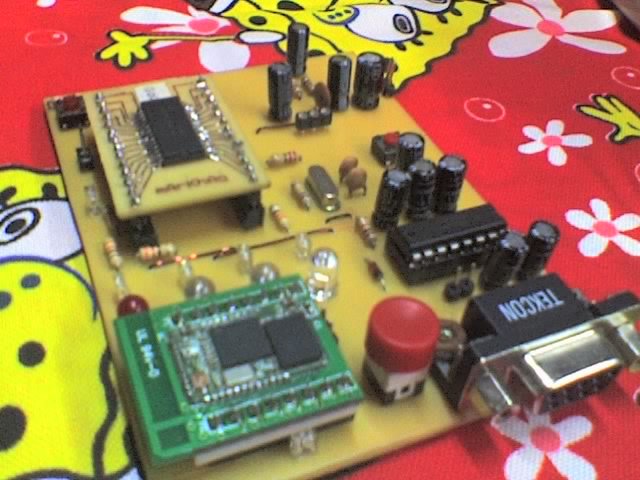
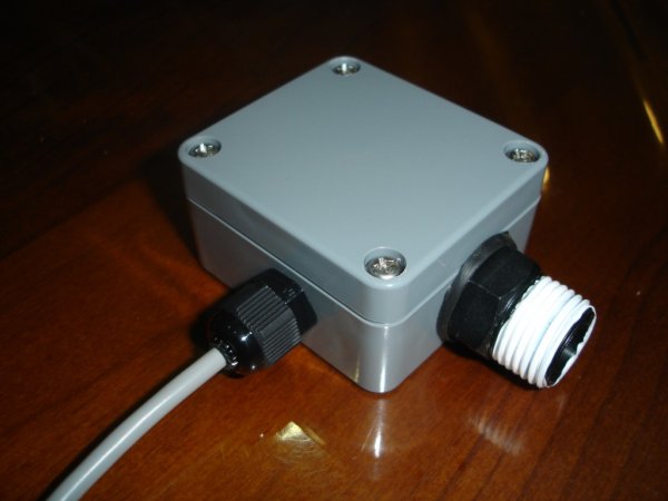
The sensor consists of two components, each housed separately and joined by shielded cable.Wireless PICAXE-based water tank level sensor

Pressure sensor

An MPX-2010DP silicon pressure sensor (temperature compensated and calibrated) is mounted inside a small project case, and screwed directly to the water outlet of the tank. Water from the tank enters in via a 12.5mm threaded nipple, which is reduced to 3mm plastic tube connected to the pressure sensor.

Air remains in the 3mm plastic tube, and is pressurised by the water coming in from the tank. The more water in the tank, the more force that is placed on the air in the tube, increasing the pressure which is read by the second component of the sensor, the sensor circuitry.
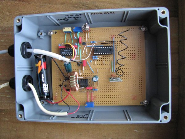
Sensor circuitry

The sensor circuitry consists of a 1.5V to 5V voltage step up circuit, an instrumentation amplifier to read the pressure sensor, a PICAXE microcontroller to convert the analog signal from the pressure sensor to a digital reading, and a 433MHz RF transmitter to transmit the water level and battery voltage to a remote base station and computer.

Apart from the use of an 18X PICAXE microcontroller, the circuit is essentially the same as the “Telemetry” version of the Silicon Chip project (schematic). I also left out the BCD switches as I only have one tank which negates the need for them, as well as the three-colour LED.

The 1.5V rechargeable battery is kept charged by a small solar panel.

The transmitted water level and battery voltage is received and displayed on an indoor base station, as well as being received by another RF receiver and 08M PICAXE built on a breadboard and connected to a PC, which stores the level in a database for displaying the water level on the web.
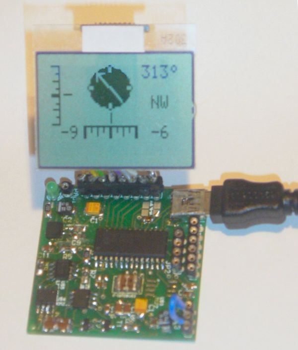
Base station

Again, the design has been based on the Silicon Chip project and the third part of their article, however the circuit was something I put together with an 18X PICAXE. I also used a “white on black” backlit LCD display, and interfaced it to the PICAXE using this PICAXE LCD interfacing guide.

My base station does not have four buttons like Silicon Chip’s, however they were not required as I only plan on reading data from one tank, and have no need to control pumps.

PC interface

The simplest part of the whole project! An 08M PICAXE reads the incoming water level and cell voltage from an RF receiver, and transmits the values out over the PICAXE serial download cable for the PC to record. There is also an LED that flashes when data is received.

If you are wondering why I used PICAXE microcontrollers, I can explain in two brief sentences. The straight forward answer is because of their ease to program, compared to a PIC. The long winded answer is ‘evolution’ – I started this project using an arduino to read the pressure sensor, then I wanted to go wireless, then I realised an arduino was overkill for one ADC conversion, plus I don’t have a PIC programmer, etc, etc.Wireless PICAXE-based water tank level sensor schematic

PICAXE sketches

Tank level sensor, PICAXE 18X
tank-receiver-lcd
tank-receiver

References and related links

Silicon Chip’s PIC-Based Water-Tank Level Meter
MPX2010 differential pressure sensor
PICAXE microcontrollers
Instrumentation amplifier on wikipedia
Practical Arduino Water tank depth sensor


For more detail: Wireless PICAXE-based water tank level sensor

Current Project / Post can also be found using:

  • projects using pic 16f877 wifi
  • transducer with pic

The post Wireless PICAXE-based water tank level sensor appeared first on PIC Microcontroller.

Roll and Temperature sensor applications using PIC18F2550

$
0
0

This page will show you how to use the TD-CMP modules in a way which fits you most.


Here are the technical specifications of the modules:

  • Compass: Resolution: 1° – Accuracy: 3°
  • Tilt/Roll: (TD-CMP02 and TD-CMP03 only) Resolution: 2° – Accuracy: 5°
  • Temperature: (TD-CMP03 only) Resolution= 1°C/F – Accuracy =1°
  • New: Sampling rate: 12,5 to 25 samples/second.
  • Easy Tilt/Roll calibration.(TD-CMP02 and TD-CMP03 only)
  • Interfaces: I²C, RS232 and mini-USB (as a HID device: PID=0461, VID= 1023)
  • Powered by USB bus or an external 5V.
  • Direct LCD readout possible. LCD contrast by user.
  • Low power LED lights when facing North (angle within 11,25° both left and right from North.)
  • USB Windows application (written in C#) available for free download.) Compatible with WinXp/Vista.
  • Source code (CCS C and C# .NET) and schematics (Eagle) can be purchased separately.
  • Module software is 100% upgradable with a simple bootloader.
  • PCB Dimensions: 40 x 41 mm or 1″57 x 1″61, weight: 10 grams.

Temperature sensor

These assembled modules are available from our online shop.

You may also purchase the bare pcb, a KIT DIY* version and the source code. KIT step-by-step construction guide.

New: compass calibration.

Schematics and pcb diagrams available for download. Last update: November 26, 2009.

DIY* = Do It Yourself

Power Source: JP4: Connect pin 2 to pin 3 to power the module directly from USB. Connect pin 1 to pin 2 when powered externally via JP3, pin 1.

New: Increase sampling speed from 12,5/second to 25/second: connect SPEED1 to SPEED2 (JP3, pin4 to JP3, pin2.)

LCD contrast Adjust: Connect pin 5, JP3 to +5V before powering up. Release when the desired the contrast is reached.


Tilt/Roll Calibration: (TD-CMP02 and TD-CMP03 only):

  • First place the module on a completely flat surface, power up.
  • Then shortly apply +5V (pin 1, JP2) to ADJUST (pin 5, JP3) Release after 1 second.
  • Check readings when applying tilt/roll to the module. Repeat the calibration procedure if necessary. Done.


Compass Calibration: (do not touch the PCB or chips whilst calibrating.)

  • First place the module on a completely flat surface, power up, head to North (position as shown in diagram and picture above), then turn the module slowly 360° (make 2-3 full clockwise and/or counter-clockwise spins.)
  • Now apply +5V (pin 1, JP2) to ADJUST (pin 5, JP3) Wait for 8-10 seconds; the LED will flash 3 times. Release the ADJUST pin from +5V. Power off and on.
  • Check compass readings when heading the module to N, S, E, W. Repeat the calibration procedure if necessary. Done.


Module RESET: apply GND to MCLR pin.


Temperature sensor: (TD-CMP03 only): The external LM335Z sensor connects to JP3 pin 4 and 6. No temperature will be displayed when the sensor is removed.


RS232 interface:

JP2 provides the interface to connect to your COM port and hyper terminal. Communications @ 115200 bpS, 8N1.

Use a level converter like the MAX3232 between the TD-CMP module and the pc serial port. See this example.

Also used for bootloading (module software update.) Check under the download section below for the latest version. Bootloading of the HEX-file can be done with Tiny Bootloader 1.91


For more detail: Roll and Temperature sensor applications using PIC18F2550

Current Project / Post can also be found using:

  • PİC C İle Sıcaklık Projeleri pdf

The post Roll and Temperature sensor applications using PIC18F2550 appeared first on PIC Microcontroller.

Humidity and temperature measurements with Sensirion’s SHT1x/SHT7x sensors using PIC18F2550 (Part 2)

$
0
0

In Part 1 of this tutorial, we discussed about Sensirion’s SHT1x and SHT7x series of humidity sensors, their interface specifications, the communication protocol used for transferring data in and out of the sensor, and the equations to convert their digital outputs to actual physical quantities. These sensors are capable of measuring temperature along with relative humidity and provide outputs in fully-calibrated digital words. We will now see how a PIC microcontroller can be programmed to communicate with these sensors, read the temperature and relative humidity data, and display the information on a character LCD.

SHT setup

Circuit Diagram

We will be interfacing the SHT11 and SHT75 sensors simultaneously to different port pins of PIC18F2550 and display the measured values of relative humidity and temperature from both on a 16×2 character LCD. The two sensors are placed next to each other and are supposed to measure the same values for relative humidity and temperature. The circuit diagram below shows the connection of the two sensors and a 16×2 character LCD to StartUSB for PIC board. StartUSB for PIC is a small development board for PIC18F2550 from mikroElektronika. The microcontroller comes preprogrammed with a bootloader, and therefore, no external programmer is required.

The LCD is operating in 4-bit mode, where the data pins D4-D7 are driven by RB4-RB7 pins of PIC18F2550. The RS and E pins are connected to RC6 and RC7 respectively. The clock lines of SHT11 and SHT75 are driven separately by RB1 and RB3 pins of PIC18F2550, respectively. On the other hand, the RB0 and RB2 pins are connected to the data pins (SDA or DATA) of SHT11 and SHT75, respectively. A decoupling capacitor (100 nF) is connected between Vcc and Gnd pins of each sensor. The PIC18F2550 microcontroller on-board StartUSB for PIC board runs at 48 MHz using the internal PLL along with an external 8.0 MHz crystal. A pull-up resistor of 10 K is required for each DATA line (in fact, the SHT11 board from mikroElektronika has pull-up resistors of 1 K on both DATA and SCK lines, but the manufacturer’s datasheet recommends 10 K).

Software

The sensor’s serial communication protocol was described in Part 1. We will implement it for PIC18F2550 using mikroC Pro for PIC. MikroElektronika provides a sample code written in mikroC for reading temperature and relative humidity from a SHT11 sensor. This code was later modified by Uroš Pešović (from Serbia) in order to account for the new conversion coefficients released by Sensirion for its version 4 sensors. I am adapting the same code for dual sensor case with some modifications that are required for our specific case.

The following subroutine is to reset the interface, in case the communication to the sensor is lost. In our case this routine will be always called before sending a new measurement command to the sensor. In order to pull the DATA line high, all you need is to define the direction of PIC port pin driving the DATA line as input. The pull-up resistor will then pull the line high. However, the same port pin direction must be defined as output and set to logic ’0′ to pull the line low.

void SHT_Reset() {
 SCL = 0;                     // SCL low
 SDA_Direction = 1;           // Define SDA as input to pull the DATA line high
 for (i = 1; i <= 10; i++)    // repeat 18 times
 SCL = ~SCL;                  // invert SCL
 }

Once the connection is reset, you need to send a Start Transmission sequence. The subroutine for this would be something like this.


For more detail: Humidity and temperature measurements with Sensirion’s SHT1x/SHT7x sensors using PIC18F2550 (Part 2)

The post Humidity and temperature measurements with Sensirion’s SHT1x/SHT7x sensors using PIC18F2550 (Part 2) appeared first on PIC Microcontroller.

Using Easy Pulse mikro with MPLAB Xpress board

$
0
0

Easy Pulse mikro is our new educational pulse sensor in a mikroBus form factor. Like our previous Easy Pulse sensors (Easy Pulse and Easy Pulse Plugin), it is also based on the principle of transmittance photoplethysmography (PPG) applied to a fingertip. The sensor consists of a pair of IR LED and photodiode to detect the cardiovascular pulse signal from the fingertip. The output of the sensor is passed through a necessary instrumentation amplifier to derive a nice and clean analog PPG waveform. The analog output is routed to the AN pin of the mikroBus connector. In this article, I will describe how to use the Easy Pulse mikro sensor with Microchip’s latest MPLAB Xpress development board for uniform ADC sampling of the analog PPG signal and sending the samples to a PC for post digital processing in order to retrieve the heart-beat rate. Currently, you can buy this sensor from our Tindie Store in United States and Elecrow Store in China.

Using Easy Pulse mikro with MPLAB Xpress board

Easy Pulse mikro

MPLAB Xpress Board

In this section, I will provide a brief overview of MPLAB Xpress board and its features.

Features

The MPLAB Xpress Evaluation Board features PIC16F18855, an 8-bit PIC processor with Core Independent Peripherals (CIPs) combined with eXtreme Low Power (XLP) technology suitable for a wide range of general purpose and low-power applications. CIPs in PIC MCUs, once initialized, can handle their tasks with zero intervention from the core (or CPU), thereby simplifying the design of embedded systems. During CIP operations, the CPU is free to perform other system tasks, if available, or can be idled and put into sleep mode to save system power. For the details of the available CIPs on PIC16F18855, refer the datasheet. The PIC16F18855 features 14 KB of program memory, 1024 bytes of RAM, and a configurable (up to 32MHz) internal oscillator. The I/O pins are brought to two rows of blank headers (0.1″ pitch) on opposite edges of the board. There are four red LEDs (with current limiting resistors) connected to I/O pins RA0 through RA3 and the EMC1001 I2C temperature sensor pre-installed on the board. A 10K potentiometer is also available (potentiometer output goes to RA4/ANA4 pin) for a quick analog-to-digital conversion demo. The availability of a mikroBus socket on board allows a simple Plug-and-Play solution for connecting mikroElektronika’s accessory boards (called Click Boards) that would greatly enhance the capability of MPLAB Xpress board.

Micro USB Using Easy Pulse mikro with MPLAB Xpress board

MPLAB Xpress Evaluation Board

For more detail: Using Easy Pulse mikro with MPLAB Xpress board

The post Using Easy Pulse mikro with MPLAB Xpress board appeared first on PIC Microcontroller.

Digital Thermometer using PIC Microcontroller and LM35 Temperature Sensor

$
0
0

Thermometer can be easily constructed using a PIC Microcontroller and LM35 Temperature Sensor. LM35 series is a low cost and precision Integrated Circuit Temperature Sensor whose output voltage is proportional to Centigrade temperature scale. Thus LM35 has an advantage over other temperature sensors calibrated in Kelvin as the users don’t require subtraction of large constant voltage to obtain the required Centigrade temperature. It doesn’t requires any external calibration. It is produced by National Semiconductor and can operate over a -55 °C to 150 °C temperature range. Its output is linearly proportional to Centigrade Temperature Scale and it output changes by 10 mV per °C.Digital Thermometer using PIC Microcontroller and LM35 Temperature Sensor

The LM35 Temperature Sensor has Zero offset voltage, which means that the Output = 0V,  at 0 °C. Thus for the maximum temperature value (150 °C), the maximum output voltage of the sensor would be 150 * 10 mV = 1.5V.  If we use the supply voltage (5V) as the Vref+ for Analog to Digital Conversion (ADC) the resolution will be poor as the input voltage will goes only up to 1.5V and the power supply voltage variations may affects ADC output. So it is better to use a stable low voltage above 1.5 as Vref+. We should supply Negative voltage instead of GND to LM35 for measuring negative Temperatures.

This article only covers the basic working of Digital Thermometer using PIC Microcontroller and LM35, and uses 5V as Vref+. If you want more accurate results it is better to select Vref+ above 2.2V. I suggest you to use  MCP1525 IC manufactured by Microchip, which will provide precise output voltage 2.5.


Suggested Readings: 

Circuit Diagram

Schematic Digital Thermometer using PIC Microcontroller and LM35 Temperature Sensor

Digital Thermometer using PIC Microcontroller and LM35 Circuit Diagram

Note: VDD and VSS of the pic microcontroller is not shown in the circuit diagram. VDD should be connected to +5V and VSS to GND.

You can download the complete MikroC Source Code and Proteus files at the bottom of this post. The Analog output voltage of LM35 temperature sensor is given to the Analog Input pin AN0 of the PIC Microcontroller. The result of the 10-bit Analog to Digital (A/D) Conversion is read using the function ADC_Read(0). This 10-bit digital value is then converted to the corresponding voltage by multiplying with 0.4887 (For More Details read: Analog to Digital Converter in PIC Microcontroller). Then the Voltage is converted to corresponding character to Display it in LCD.

For more detail: Digital Thermometer using PIC Microcontroller and LM35 Temperature Sensor 


The post Digital Thermometer using PIC Microcontroller and LM35 Temperature Sensor appeared first on PIC Microcontroller.


Wearable sensors analyze your sweat

$
0
0

Sodium. Potassium. Glucose. Lactate. Engineers at the University of California, Berkeley are focusing on measuring these components of sweat in an attempt to open an additional window into an individual’s health and well-being. A new device is able to calibrate the data based on skin temperature and transmit the information wirelessly in real time to a smartphone. The results of a new study of the wearable technology have been published in the journal Nature.
Wearable sensors analyze your sweat
“Human sweat contains physiologically rich information, thus making it an attractive body fluid for noninvasive wearable sensors,” says Ali Javey, a UC Berkeley professor of electrical engineering and computer sciences, and senior author of the study. “However, sweat is complex and it is necessary to measure multiple targets to extract meaningful information about your state of health. In this regard, we have developed a fully integrated system that simultaneously and selectively measures multiple sweat analytes.”

Javey and his research team developed a prototype that comprises a flexible printed circuit board holding five sensors. The device was attached to “smart” wristbands and headbands and used on 26 volunteers who performed various exercises of differing levels of intensity, and for varying lengths of time, both indoors and outdoors. The data collected was then processed and wirelessly transmitted using Bluetooth to a smartphone.
The researchers are not alone in their quest to squeeze every drop of data possible out of human perspiration. A “sweat test,” which measures the amount of chloride in an individual’s sweat, is considered the “gold standard” for diagnosing cystic fibrosis, a genetic disease that causes chronic lung infections and respiratory issues. In addition, a team at the University of Cincinnati’s Novel Devices Lab, working with scientists from the U.S. Air Force Research Laboratory, has developed a patch that stimulates skin and gathers data from sweat. The research began five years ago with the intent to find a convenient way to monitor an airman’s response to disease, medication, diet, injury, stress, and other physical changes during military training and missions.

Javey concedes that sweat sensors will never be as accurate as blood tests. “Our bodies closely control the molecular composition of our blood, but the content of our sweat is more variable and is sometimes influenced by microbes on our skin — so the medical relevance of the information that sweat provides will need to be rigorously tested,” he explains. “However, sweat does have an advantage: taking blood samples with a needle is not a practical means of assessing health on a minute-by-minute basis.”

For more detail: Wearable sensors analyze your sweat

The post Wearable sensors analyze your sweat appeared first on PIC Microcontroller.

Interfacing Ultrasonic Distance Sensor : ASCII Output with PIC Microcontroller

$
0
0

In some of our projects, we may want to measure the distance of an object from a point. Ultrasonic Distance Sensors are the best sensor which provides stable, accurate, precise, non-contact distance measurements from 2cm to 4m. Ultrasonic Sensors can be used to measure distance between moving or stationary objects. Being very accurate and stable, these devices find large number of applications in robotics fields. For example it can be used as an excellent replacement for IR sensors in  a Micromouse. In this tutorial we will lean to interface an Ultrasonic Distance Sensor with PIC Microcontroller.Interfacing Ultrasonic Distance Sensor ASCII Output with PIC MicrocontrollerHere for demonstration we are using Rhydolabz Ultrasonic Distance Sensor with ASCII Output. It can be easily interfaced with a PIC Microcontroller using USART by just connecting the output pin of the sensor to RX pin of the microcontroller. In every 500ms this sensor transmits an ultrasonic burst and listens for its echo. The sensor sends out ASCII value corresponds to the time required for the ultrasonic burst to return to the sensor. The UART of the sensor is operates at a baud rate 9600 and the sensor can be powered by  a 5V DC Supply. The ASCII output of the sensor will be equal to the distance to the obstacle in centimeter (cm).

The sensor has three pins…

  • Vcc  – +5V DC Supply to the Sensor
  • GND –  Ground Level of the Power Supply
  • SIG – Signal, Serial Data Out

Circuit DiagramSchematic Interfacing Ultrasonic Distance Sensor ASCII Output with PIC Microcontroller

The sensor outputs distance in centimeter (cm) via USART. The output format can be found from the datasheet of the sensor as follows.

For more detail: Interfacing Ultrasonic Distance Sensor : ASCII Output with PIC Microcontroller

The post Interfacing Ultrasonic Distance Sensor : ASCII Output with PIC Microcontroller appeared first on PIC Microcontroller.

Line follower robot using microcontroller

$
0
0

It follow a black line automatically and it also turn it direction according to black line. Liner follower robot is very famous project at university level among electrical, electronics, computer and software engineering students. There are a lot of competitions held every year in engineering universities related to robotics. But for first year engineering students, Liner follower robot is very popular.Because it is easy to make and can be easily ready to run with in  minimum time.Line follower robot using microcontroller

Applications of line follower robot

Line follower robot which is usually make at university level is just to make students familiar with the field of robotic. But actual robots use in fields are much more complex and they can perform very complicated task in industry. It is not possible to make a practical robot at university level. That’s why international robotics club encourage students to make simple robots like Liner follower robot, obstacle avoided robot, metal detection robot to get basic understanding of practical robots.In this article I have presented you an idea of Liner follower robot. How to make line follower robot using microcontroller.

Circuit working of line follower robot:

Block diagram of line follower using pic microcontroller is shown below. As I have clearly mentioned in block diagram. Two motors are used. One motor is attached with left Tyre of robot and another motor is attached with right Tyre of robot. Front wheel of Line follower robot is freely moving wheel. Motor driver IC is used to rotate both motors either clock wise or anti clock wise direction according to turning direction of Line follower robot. L298 motor driver IC is used as a motor driver IC. Microcontroller Atmega16 is used to give control signals to motor driver IC according to sensors output. Light dependent resistor in combunation with light emitting diode is used to sense black line. In case robot goes off from black line, respective sensor operate and microcontroller sense its value and take control control actions by turn motors either clock wise or anticlock wise.

Sensors circuit diagram for line follower robot

I have already mentioned sensors are used to sense black line. I have used seven sensors in this project. But you can also use 3 , 5 sensors according to width of black line. Light dependent resistor in combination with light emitting diode is used to sense either line follower robot is on black line or off line. Circuit diagram of single sensor is shown below. but you should connect all seven sensors on single strip with a distance of 2-3 cm between each set LDR and LED to get better results of line follower robot.

Schematic Line follower robot using microcontroller

sensor for line follower robot

For more detail: Line follower robot using microcontroller

The post Line follower robot using microcontroller appeared first on PIC Microcontroller.

Making a simple clap switch

$
0
0

A clap switch is a fun project for beginners. It switches on and off electrical appliances with a sound of clapping hands. Today we will discuss about making a simple clap switch that operates when it detects two clapping sounds in a row. It uses an electret microphone as a transducer for converting a clapping sound into an electrical signal. The microcphone output is amplified by a transistor and is then sent to the PIC12F683 microcontroller which performs an ON/OFF switching action when valid claps are detected.

Making a simple clap switch

Simple clap switch using a condenser mic and PIC microcontroller

Theory

The clap switch requires a transducer at the input to convert sound vibrations from clapping hands into electrical energy. An electret microphone or simply mic (OBO-04FN-0B) is used for this purpose. The output from the mic is very low in magnitide and so we need an amplifier circuit to boost the detected sound signal. The following circuit diagram shows the mic along with a single transistor amplifier. When there’s no sound, the collector voltage (Vout) of the transistor, which is saturated, is approximately 0.2V. When the mic detects a clap sound, the voltage across it drops suddenly. Since the condenser mic’s output voltage is coupled to the base of the transistor through capacitor C1, the base-emitter voltage is also lowered and as such the base-emitter junction is less forward biased or cutoff (in case of high clap sound). Therefore, every time a clapping sound is detected, there is a sudden peak arising at the collector voltage.

Schematic Making a simple clap switch

Sensor part

The following picture shows the peaks in the collector voltage due to multiple clap sounds. You can see the peak voltage can go as high as 4.0V depending on the loudness of the clap. This waveform of the collector voltage is captured using Digilent’s Analog Discovery device.

For more detail: Making a simple clap switch

The post Making a simple clap switch appeared first on PIC Microcontroller.

Temperature sensor using PIC16F877A microcontroller

$
0
0

OBJECTIVE:

Components:

There are many temperature sensors available in market. But LM35 temperature sensor is used in this project. It is cheapest in price and one can easily find it in market. There are many other advantages of LM35 like:

 Temperature sensor using PIC16F877A microcontroller
  • It is more efficient than thermistor
  • It is made up of integrated circuit hence no chance of damaging to internal circuitry.
  • It draws current only in micro Amperes.

Only 5 volt power supply is required for LM35 and there is no need of extra circuitry to operate it. PIC16F877A microcontroller is used to read temperature value. 16X2 LCD is used to display temperature value on LCD. Code of this project written in Mikro C compiler.

Implementation:

LM35 temperature sensor converts temperature into its proportional analog voltage value. LM35 is three terminal device.Pin number one and three are for 5-volt voltage supply. Pin two is analog voltage output with respect to temperature value.Relation between measured temperature and analog output voltage is:

1oC = 10m volt

Hence for every 1 degree increase in temperature there will be a increment of 10m volt in output voltage of LM35 sensor. PIC16F877A microcontroller is used to measure analog voltage value.  PIC16F877A  microcontroller built in ADC (analog to digital converter) is used to measure analog voltage.  PIC16F877A PORTA have seven built in ADC channels. So one can interface up to seven sensors with this microcontroller very easily.I will post a project on green house system.In green house system project I have used four ADC channels to measure temperature , light, humidity and moisture. Coming back to our digital thermometer, ADC has been used to read analog voltage. After reading ADC value, using voltage and temperature relationship voltage is converted back into temperature. A conversion factor is used to convert voltage back into temperature. All these conversion has been done through programming. LCD is connected to PORTB of  PIC16F877A microcontroller. I will discuss it in programming part. LCD is used to display temperature value.

Circuit diagram:

Proteus is used for simulation. Following is a circuit diagram of Digital temperature sensor:

Schematic Temperature sensor using PIC16F877A microcontroller

temperature sensor circuit diagram

As shown in above figure both temperature sensor and LCD is displaying same values of temperature. To ensure protection of LM35 and microcontroller you can connect 80k ohm resistor parallel to output of temperature sensor.

For more detail: Temperature sensor using PIC16F877A microcontroller

The post Temperature sensor using PIC16F877A microcontroller appeared first on PIC Microcontroller.

Viewing all 406 articles
Browse latest View live


<script src="https://jsc.adskeeper.com/r/s/rssing.com.1596347.js" async> </script>