Quantcast
Channel: sensor | Battery Guide
Viewing all 406 articles
Browse latest View live

Make your own motion sensor alarm with SMS feature using PIC18F2550

$
0
0

MikroEleketronika demonstrates how to build a simple home alarm system that has the capability of sending SMS to a predefined cell phone number when intrusion is detected.

motion sensor alarm

This project is based on StartUSB for PIC board, a small development board for PIC18F2550, which is preprogrammed with an USB bootloder so that no additional programmer is required to load the firmware. The SMS portion uses a SmartGM862 Board, which is a full-featured development tool for the Telit’s GM862 GSM/GPRS module. All the boards required for this project can be purchased as SMS Home Alarm Kit from mikroElektronika. A demonstration software for PIC is also available for free. They are offering free shipping now.


For more detail: Make your own motion sensor alarm with SMS feature using PIC18F2550

Current Project / Post can also be found using:

  • home automation program for microcontroller

The post Make your own motion sensor alarm with SMS feature using PIC18F2550 appeared first on PIC Microcontroller.


Digital humidity sensor using PIC microcontroller

$
0
0

Digital humidity sensor with LCD display using PIC microcontroller

Digital humidity sensor with LCD display is used to measure relative percentage  of water vapors in air. HS1101 capacitive humidity sensor is interfaced with PIC16F877A microcontroller to measure humidity and LCD is used to display percentage humidity in air.For humans there is certain limit for water vapors presence in air. Above that limit relative humidity may cause problems to human health.Digital humidity sensor using PIC microcontroller

Applications of digital humidity sensors

Humidity sensors have many application in industry and domestic areas. Humidity means presence of water vapors in air. Percentage of water vapors in air should be with in safety limit. Otherwise It have harmful physical and chemical effects on human beings and also in industrial products. Humidity sensors have major applications in agriculture ,chemical, oil, gas and medical industry. For example in agriculture industry humidity sensor is used to measure moisture in fields. There are also many other application of humidity sensor.You can search them om Google.

digital Humidity sensor selection

When you search on Google, you will come across many humidity sensors. All these humidity sensors have their advantage and disadvantage. But I used capacitive HS1101 humidity sensor in this project. What is meant by capacitive humidity sensor? All capactive senors give output in capacitive form.They change their capacitance with respect to change in sensing parameter like in HS1101 sensor sensing parameter is amount of water vapors in air. The reason why I used this humidity sensor?  Because

  • It can be used for highly sensitive applications.
  • less cost
  • easy to interface with microcontroller with small extra circuitry
  • No calibration is required
  • It can be easily used for home appliances and industrial control system.

How to use HS1101 digital humidity sensor

HS1101 is a  capacitive humidity sensor, so it can be used with 555 timer circuit to generate square wave of different frequency. I assume you know about 555 timer IC and its use.

Schematic Digital humidity sensor using PIC microcontroller

humidity sensor circuit with external circuitry

As shown in above figure, variable capacitor is used in place of humidity sensor for simulation purpose. Becuase HS1101 simulation model is not available in Proteus. Above circuit is used as a signal conditioning circuit to convert one form of parameter to its other proportional parameter so that it can be easily interfaced with any digital system or microcontroller. It is not possible for any microcontroller to read change in capacitance directly. That why above circuit is used to convert changing capacitance of HS1101 into sqaure wave whose frequency changed according to change in capacitance .

For more detail: Digital humidity sensor using PIC microcontroller

Current Project / Post can also be found using:

  • DIGITAL HUMIDITU SENSOR USING PIC MICROCONTROLLER

The post Digital humidity sensor using PIC microcontroller appeared first on PIC Microcontroller.

Green house intelligent control system

$
0
0

Green house intelligent control system is designed to protect the plants from more cool and hot weather and additional control system is included to save power by making fans and lights automatically turn on and off with the help of intelligent control system. In this project, the intelligent control system is developed using microcontroller and sensors. Green house system has a very important use now a days in the agriculture field.Some plants need the specific amount of water for their proper growth and more  productivity, therefore farmer should provide them the proper quantity of water. But it’s difficult for the farmer to get a estimation for quantity of moisture in soil. But in this project moisture sensor is used to to provide this facility with a intelligent control system.Green house intelligent control system

Block diagram below shows the main functionality of green house intelligent control system. Four sensors are used to measure different parameters of green house system which includes temperature sensor, light sensor, humidity sensor, moisture sensor. Four relays are used to control four respective loads as given below:

LM35 Temperature sensor :

When temperature becomes greater than 25 degree, respective relay become energize to operate the fan and when temperature becomes lower than 20-degree relay turn off the fan by getting control signals from microcontroller. PIC16F877A microcontroller analog to digital converter module is used to read temperature value and to operate relay which in turn operate the fan. To know more about temperature sensor and its working, go through the following article :

Digital temperature sensor using pic microcontroller
Light sensor :

Light dependent resistor is used as a light sensor. LDR is kind of variable resistor which resistance changes with the change in light intensity. So LDR resistance is converted into intensity of light by using LDR resistance and intensity of light formula. PIC16F877A microcontroller is used to measure intensity of light. When intensity of light fall under a certain limit, microcontroller provide signal to relay to turn on light and when intensity of light raise upto a certain limit , microcontroller provide signal to relay to turn off fan. So light sensor is used to add automatic light switching functionality in the green house system, if you don’t have much money to afford a gardener, then you can use green house intelligent control system to make your green house self-operating.

HS1101 Humidity sensor :

Humidity sensor is used to check level of moisture in air Because greater or less humidity level in air can also effect growth of plants. Humidity sensor HS1101 is used to measure level of moisture in air. HS1101 is a capacitative type humidity sensor, So additional circuit is used to convert change in capacitance of humidity sensor into frequency and frequency is measured with the help of microcontroller. Measured frequency is converted back into humidity using a algorithm in microcontroller programming. To know more about humidity sensor and its working, I suggest you to go through following article :

Digital humidity sensor using pic microcontroller 

If humidity becomes greater than a specified limit, microcontroller gives a signal to respective relay to turn on sprinter which is used to maintain a humidity level in the air and when humidity level comes back to a normal limit, microcontroller gives a signal to respective relay to turn off sprinter.


Moisture sensor :

Moisture sensor is used to measure level in soil. A wire strip is used to measure moisture of soil. Wire strip has a specific resistance at specific moisture, but when moisture increases, the resistance of wire strip starts decreasing and similarly when moisture decreases, resistance become higher. PIC16F877A used to measure moisture level and to turn on and off water pump with the help of relay.

Block diagram of complete project is shown below:

Schematic Green house intelligent control system

simulation of green house system

For more detail: Green house intelligent control system

The post Green house intelligent control system appeared first on PIC Microcontroller.

Controlling a Servo with a PICAXE and an IR Sensor

$
0
0
Learn how to combine a PICAXE, IR sensors, and a servo motor to create a device that responds to a moving stimulus. Spoilers: I hook it up to eyeballs that can follow a finger.

Related Information


What’s a PICAXE?

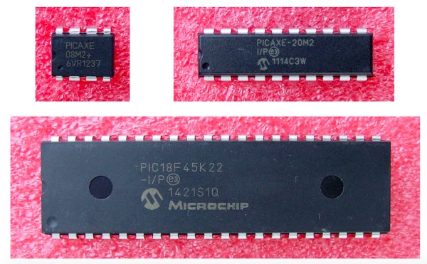
PICAXEs are PIC microcontrollers that have been preloaded with a bootstrap code that allows programming in BASIC language. All About Circuits provides a series of articles that serve as a guide to choosing and using any of the chips in the PICAXE family. This article will provide an excellent starting point and will lead you to other articles in the series.Controlling a Servo with a PICAXE and an IR Sensor

Project Overview

This project consists of building a circuit using common IR (infrared) LEDs to produce IR emissions and an IR phototransistor to detect reflected IR light. The voltage from the phototransistors varies with the intensity of the IR light received. A specially programmed PICAXE microcontroller converts this analog voltage to a digital format and stores it for comparison with the output from other IR phototransistors.

Based on the relative levels of the IR light, the PICAXE signals a servo motor to rotate to a predetermined position. Thus, reflected IR light can be used to control physical movements.


What’s a Servo?

Servos, or more specifically servomotors, are electromechanical devices that consist of (1) an electric motor with an accessible output shaft, (2) a mechanism to determine the rotary position of the output shaft, and (3) electronic circuitry to receive control signals and position the output shaft accordingly.

One of the most familiar uses of small servos is to move the throttle and control surfaces of RC (radio control) airplanes. Servos are available in a variety of sizes, shapes, and capabilities. A servo suitable for use in this project is the Tower-Pro MG996R, two of which are shown in the photo below.Motor Controlling a Servo with a PICAXE and an IR Sensor

The MG996R servo operates on 4.8V to 7.2V, and can draw from 500 mA to almost a full ampere depending upon its load. The output shaft covers a range of 120 degrees (60 degrees each side of center.) For a more complete description, download and read the datasheet. A little on-line research will produce all the information you can imagine about servomotors.

For more detail: Controlling a Servo with a PICAXE and an IR Sensor

The post Controlling a Servo with a PICAXE and an IR Sensor appeared first on PIC Microcontroller.

Behavior Based Artificial Intelligent Mobile Robot with Sharp GP2D120 Distance Measuring Sensor – BRAM Part 2

$
0
0

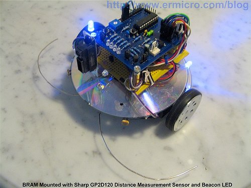
What is the intelligent anyway; could we categories how the bees building their tiny hexagonal compound nest, ants searching for their food or birds migration using precision navigation over continental are the intelligent acts; or we as the human being with our cultures and civilizations is the only one that can be categories as the intelligent being? These kinds of question probably will not have satisfied answer as the answer is more philosophy terms rather than physics or mathematics law; therefore I think anyone could give their own opinion to this question.Behavior Based Artificial Intelligent Mobile Robot with Sharp GP2D120 Distance Measuring Sensor – BRAM Part 2

Continuing our tutorial about BRAM (Building BRAM your first Autonomous Mobile Robot using Microchip PIC Microcontroller – Part 1); this time we will learn how to program BRAM brain and at the same time we learn how to use the Microchip PIC16F690 microcontroller EUSART (Enhanced Universal Synchronous Asynchronous Receiver Transmitter) peripheral for debugging BRAM program; later on we will add the distance measuring sensor for enhancing the obstacle avoidance capabilities to BRAM; this time we will use sharp GP2D120 analog distance measuring sensor.

As you learn through these two tutorials, building BRAM is not just a matter of building a robot; which of course is cool (…yeah…I’ve build a robot) but is more than that; building a robot required you to use your imagination and knowledge about how to build the robot chassis, choosing the right stuff to put on your robot, maximizing the microcontroller’s peripherals to support your robot and finally programming your robot; this kind of knowledge is very important in the embedded system control used in many industries.

BRAM Steering

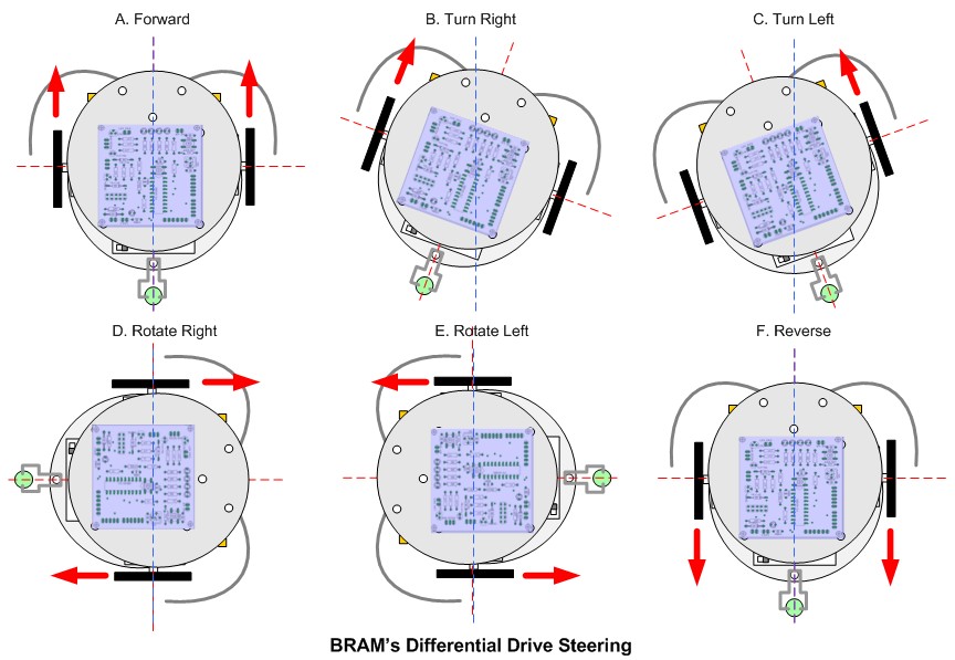
BRAM steering method use what is called “differential drive“, this method use two DC motor mounted in fixed positions on the left and right side of BRAM chassis; each motor can rotate independently both in forward or reverse direction. By controlling these two DC motors rotate direction; we could control how BRAM move.Schematic Behavior Based Artificial Intelligent Mobile Robot with Sharp GP2D120 Distance Measuring Sensor – BRAM Part 2For more detail: Behavior Based Artificial Intelligent Mobile Robot with Sharp GP2D120 Distance Measuring Sensor – BRAM Part 2

Current Project / Post can also be found using:

  • robotic automation project

The post Behavior Based Artificial Intelligent Mobile Robot with Sharp GP2D120 Distance Measuring Sensor – BRAM Part 2 appeared first on PIC Microcontroller.

Adds sensor nat Semi front end ICs

$
0
0

Description


The LMP90100/LMP90099/LMP90098/LMP90097 are highly integrated, multi-channel, low power 24-bit Sensor AFEs. The devices features a precision, 24-bit Sigma Delta Analog-to-Digital Converter (ADC) with a low-noise programmable gain amplifier and a fully differential high impedance analog input multiplexer. A true continuous background calibration feature allows calibration at all gains and output data rates without interrupting the signal path. The background calibration feature essentially eliminates gain and offset errors across temperature and time, providing measurement accuracy without sacrificing speed and power consumption.

Another feature of the LMP90100/LMP90099/LMP90098/LMP90097 is continuous background sensor diagnostics, allowing the detection of open and short circuit conditions and out-of-range signals, without requiring user intervention, resulting in enhanced system reliability.

Two sets of independent external reference voltage pins allow multiple ratiometric measurements. In addition, two matched programmable current sources are available in the LMP90100/LMP90098 to excite external sensors such as resistive temperature detectors and bridge sensors. Furthermore, seven GPIO pins are provided for interfacing to external LEDs and switches to simplify control across an isolation barrier.

Collectively, these features make the LMP90100/LMP90099/LMP90098/LMP90097 complete analog front-ends for low power, precision sensor applications such as temperature, pressure, strain gauge, and industrial process control. The LMP90100/LMP90099/LMP90098/LMP90097 are ensured over the extended temperature range of -40°C to +125°C and are available in a 28-pin HTSSOP package with an exposed pad.

Features

  • 24-Bit Low Power Sigma Delta ADC
  • True Continuous Background Calibration at all gains
  • In-Place System Calibration using Expected Value programming
  • Low-Noise programmable gain (1x – 128x)
  • Continuous background open/short and out of range sensor diagnostics
  • 8 output data rates (ODR) with single-cycle settling
  • 2 matched excitation current sources from 100 µA to 1000 µA (LMP90100/LMP90098)
  • 4-DIFF / 7-SE inputs (LMP90100/LMP90099)
  • 2-DIFF / 4-SE inputs (LMP90098/LMP90097)
  • 7 General Purpose Input/Output pins
  • Chopper-stabilized buffer for low offset
  • SPI 4/3-wire with CRC data link error detection
  • 50 Hz to 60 Hz line rejection at ODR ≤13.42 SPS
  • Independent gain and ODR selection per channel
  • Supported by Webench Sensor AFE Designer
  • Automatic Channel Sequencer

Nat Semi adds sensor front end ICs

Key Specifications

  • ENOB/NFR Up to 21.5/19 bits
  • Offset Error (typ) 8.4 nV
  • Gain Error (typ) 7 ppm
  • Total Noise < 10 µV-rms
  • Integral Non-Linearity (INL max) ±15 ppm of FSR
  • Output Data Rates (ODR) 1.6775 – 214.65 SPS
  • Analog Voltage, VA +2.85 to +5.5 V
  • Operating Temp Range -40°C to 125 °C
  • Package 28 Pin HTSSOP exposed pad

All trademarks are the property of their respective owners. TRI-STATE is a trademark of Texas Instruments.

National semiconductor has covered most analogue sensors by introducing two signal conditioning chips.

LMP90100 is for thermocouples, variable resistance, current loop and voltage sensors, and includes a 24bit ADC.

LPM91000 is for electrochemical sensors, for example gas detectors, and feeds an external ADC.

“Sensor-based system designs are time-consuming and complicated to develop, requiring an optimal design for each system,” said Anita Ganti, precision systems business director at National. “Until now, designers have developed customised analogue solutions that took weeks or even months to develop, but we can now help them get to market more quickly.”

The firm has coined the phrase ‘sensor AFEs‘ (analogue front ends) to describe the products, which are the first of a family, said Ganti.

Key to applying the devices is an on-line data base – currently holding 200 sensors – that can download appropriate setting parameter directly into associated development boards on the bench.


For more read: adds sensor Nat Semi front end ICs

The post Adds sensor nat Semi front end ICs appeared first on PIC Microcontroller.

DHT22 (AM2302) Digital Humidity and Temperature Sensor Proteus Simulation

$
0
0
Like the DHT11, the DHT22 is a digital humidity and temperature sensor which has more benefits than DHT11 like: High precision and range.
If we want to understand this topic we have to read the DHT22 datasheet and see how this device works and its characteristics.
Note that the DHT22 is available only on Proteus version 8.1 or higher, version 8.0 or later will not work therefore you have to update your version.
From the datasheet:
1-wire bus is used for communication between MCU and DHT22, which means that the sensor communicates over only one-wire with the master device (microprocessor or microcontroller), by this wire the DHT22 sends/receives data to/from the master device.
Illustration of our 1-wire bus:DHT22 (AM2302) Digital Humidity and Temperature Sensor Proteus Simulation
DATA=16 bits RH data+16 bits Temperature data+8 bits check-sum
Example: MCU has received 40 bits data from AM2302 as
0000 0010 1000 1100 0000 0001 0101 1111 1110 1110
16 bits RH data 16 bits T data check sum
Here we convert 16 bits RH data from binary system to decimal system,
0000 0010 1000 1100 → 652
Binary system Decimal system
RH=652/10=65.2%RH
Here we convert 16 bits T data from binary system to decimal system,
0000 0001 0101 1111 → 351
Binary system Decimal system
T=351/10=35.1℃
When highest bit of temperature is 1, it means the temperature is below 0 degree Celsius.
Example: 1000 0000 0110 0101, T= minus 10.1℃
16 bits T data
Sum=0000 0010+1000 1100+0000 0001+0101 1111=1110 1110
Check-sum=the last 8 bits of Sum=1110 1110
When MCU send start signal, DHT22 change from standby-status to running-status. When MCU finishes sendingthe start signal, DHT22 will send response signal of 40-bit data that reflect the relative humidity and temperatureto MCU. Without start signal from MCU, DHT22 will not give response signal to MCU. One start signal for one
response data from DHT22 that reflect the relative humidity and temperature. DHT22 will change to standby status when data collecting finished if it don’t receive start signal from MCU again.
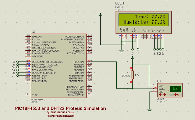
Interfacing PIC18F4550 with DHT22 (AM2302) Proteus simulation:
The picture below shows a Proteus circuit diagram of the simulation:
Internal oscillator is used at 8MHz and MCLR pin is disabled.Schematic DHT22 (AM2302) Digital Humidity and Temperature Sensor Proteus Simulation

The post DHT22 (AM2302) Digital Humidity and Temperature Sensor Proteus Simulation appeared first on PIC Microcontroller.

ADI moves MEMS gyro sensor to tactical grade

$
0
0

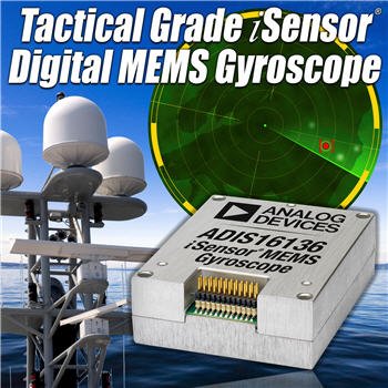
The ADIS16488 iSensor® MEMS IMU is a complete inertial system that includes a triaxis gyroscope, a triaxis accelerometer, triaxis magnetometer and pressure sensor. Each inertial sensor in the ADIS16488 combines industry-leading iMEMS® technology with signal conditioning that optimizes dynamic performance. The factory calibration characterizes each sensor for sensitivity, bias, alignment, and linear acceleration (gyroscope bias). As a result, each sensor has its own dynamic compensation formulas that provide accurate sensor measurements.

The ADIS16488 provides a simple, cost-effective method for integrating accurate, multiaxis inertial sensing into industrial systems, especially when compared with the complexity and investment associated with discrete designs. All necessary motion testing and calibration are part of the production process at the factory, greatly reducing system integration time. Tight orthogonal alignment simplifies inertial frame alignment in navigation systems. The SPI and register structure provide a simple interface for data collection and configuration control.

The ADIS16488 uses the same footprint and connector system as the ADIS16375, which greatly simplifies the upgrade process. It comes in a module that is approximately 47 mm × 44 mm × 14 mm and has a standard connector interface.

  • Triaxial, digital gyroscope with digital range scaling
    – ±450°/sec dynamic range
    – <0.05° orthogonal alignment
    – ~6°/hr in-run bias stability
    – 0.3°/√hr angular random walk
    – 0.01% nonlinearity
  • Triaxial, digital accelerometer, ±18 g
  • Triaxial, delta-angle and delta velocity outputs
  • Triaxial, digital magnetometer, ±2.5 gauss
  • Digital pressure sensor, 300 mbar to 1100 mbar
  • Fast start-up time, ~500 ms
  • Factory-calibrated sensitivity, bias, and axial alignment
    – Calibration temperature range: −40°C to +70°C
  • SPI-compatible serial interface
  • See datasheet for additional features

ADI moves MEMS gyro sensor to tactical grade

Analog Devices has introduced a new MEMS IMU (inertial measurement unit) in its iSensor range and the signficance is this is a tactical grade 10-degree-of-freedom (DoF) sensor.

“For industrial, military, and medical equipment designers who require the most accurate detection and control of motion in order to stabilize or navigate their applications, the ADIS16488 tactical grade IMU offers performance levels previously only available to those with unlimited budgets,” said Bob Scannell, iSensor business development manager, MEMS/Sensors technology group at Analog Devices.

The ADIS16488 integrates a tri-axis gyroscope, tri-axis accelerometer, tri-axis magnetometer and a pressure sensor into a single package.

“With equal or better performance to legacy high-end IMUs on key measures such as bias stability and angular random walk, the ADIS16488 provides better performance on the often more critical parameters of vibration-rectification, linearity, and bandwidth while consuming one-quarter the power, and at one-tenth the cost,” said Scannell.

The ADIS16488 iSensor 10-DoF MEMS IMU is a complete inertial measurement system that combines ADI’s high performance iMEMS® technology and sensor-signal processing expertise to optimize the IMU’s 10-DoF dynamic performance.

Operation is fully autonomous, including all embedded compensations, with valid data available from the SPI interface 500ms after applying power.

Calibration is carried out at the factory, and there is a Blackfin processor for configuring the interface for tuning embedded filtering and other diagnostics


For more read: ADI moves MEMS gyro sensor to tactical grade


The post ADI moves MEMS gyro sensor to tactical grade appeared first on PIC Microcontroller.


Chip senses gesture through electric fields

$
0
0

Description

The PS25401A is an ultra high impedance non-contact solid state electric potential sensor. It can be used to detect field disturbance due to the movement of a near-by object. This functionality can be employed in a range of applications including security motion sensors and non-contact electric switches for lighting, door opening, toys etc

The device uses active feedback techniques to both lower the effective input capacitance of the sensing element (Cin) and boost the input resistance (Rin). These techniques are used to realize a sensor with a frequency response suitable for remote sensing applications.

Also known as PS25401A EPIC Sensor.

Features

  • Ultra high effective input resistance, typically 20GΩ.
  • Effective input capacitance as low as 15pF.
  • Upper 3dB point typically 10kHz.
  • Operates with bipolar power supply from ±2.4V to ±4.0V.
  • Sensors supplied in a custom package with exposed pins for surface mount assembly

Chip senses gesture through electric fields

Plessey has released an electrostatic field sensing chip for security, switching and gaming applications.

It is the second member of the firm’s EPIC (electric potential IC) range, the first of which was a non-contact EEG (heart waveform) monitor.

“We have optimised the base layout of the EPIC sensor chip such that discrete movements of the human body can be detected with a range of up to several metres,” said Plessey CTO Dr Keith Strickland. “For example, the sensor can be configured to detect the proximity of a hand or to detect specific hand motions depending on the chip variant and the appropriate selection of circuit components external to the sensor.”

Called PS25401, the new chip can detect movement through walls, said Plessey, and can drive a relay “to act as a simple non-touch electric switch. It can also be used to replace, or as an adjunct to, a passive infra-red (PIR) sensor.”


For more read: Chip senses gesture through electric fields

The post Chip senses gesture through electric fields appeared first on PIC Microcontroller.

ST shrinks MEMS gyro by 50% for smart clothes

$
0
0

The L3GD20H is a low-power three-axis angular rate sensor.

It includes a sensing element and an IC interface able to provide the measured angular rate to the external world through digital interface (I2C/SPI).

The sensing element is manufactured using a dedicated micromachining process developed by ST to produce inertial sensors and actuators on silicon wafers.

The IC interface is manufactured using a CMOS process that allows a high level of integration to design a dedicated circuit which is trimmed to better match the sensing element characteristics.

The L3GD20H has a full scale of ±245/±500/±2000 dps and is capable of measuring rates with a user selectable bandwidth.

The L3GD20H is available in a plastic land grid array (LGA) package and can operate within a temperature range from -40 °C to +85 °C.

Key Features

  • Wide supply voltage, 2.2 V to 3.6 V
  • Wide extended operating temperature range (from -40 °C to 85 °C)
  • Low voltage compatible IOs, 1.8 V
  • Low power consumption
  • Embedded power-down
  • Sleep mode
  • Fast turn-on and wake-up
  • Three selectable full scales up to 2000 dps
  • 16 bit rate value data output
  • 8 bit temperature data output
  • I2C/SPI digital output interface
  • 2 dedicated lines (1 interrupt, 1 data ready)
  • User enable integrated high-pass filters
  • Embedded temperature sensor
  • Embedded 32 levels of 16 bit data output FIFO
  • High shock survivability
  • ECOPACK® RoHS and “Green” compliant

ST shrinks MEMS gyro by

STMicroelectronics has recently introduced its smallest and lowest power chip-scale MEMS gyroscope for advanced motion-sensing applications.

The L3GD20H gyroscope measures 3x3mm and 1mm high, the device occupies little over half the volume of its predecessor.

One application is in so-called smart clothing which can be used in sports training aids, or medical therapy.

“Miniaturised, low-power sensors enable smart electronics to be used in items such as clothes or sports equipment, creating opportunities for exciting new products and services,” said Roberto De Nuccio, business development manager for ST’s motion MEMS division.

Other target applications are in prosthetics, medical instruments, goods tracking and power tools.

The gyroscope also draws 25% lower current than the previous generation of devices.

It has three selectable full-scale ranges (245/500/2000dps). Interfaces include I2C/SPI.

Internal low- and high-pass filters have user-selectable bandwidth and there is an on-chip temperature sensor and FIFO.

For more read: ST shrinks MEMS gyro by 50% for smart clothes

The post ST shrinks MEMS gyro by 50% for smart clothes appeared first on PIC Microcontroller.

iProtoXi Aistin: Multi-Modular Sensor Platform

$
0
0

Internet of My Own Things

Intelligence without ambition is a bird without wings. –Salvador Dali
The Internet of Things has a different meaning for different people. For some, it means monitoring room temperatures from a mobile phone, whereas for other, it is controlling garden lighting from a laptop computer. For sports-minded people, it might mean logging their heart rate in real-time to a cloud service. Is there a common denominator between this wide range of different applications?

iProtoXi Aistin: Multi-Modular Sensor Platform

Our answer is Aistin. Instead of functionally limited ready-made IoT-sets, or flexible but unpractical self-wired desktop hassles, we wanted to inspire people to create new mobile products by providing the best that can be achieved with current technology:

  • Compactness – create tiny wrist worn devices instead of desktop monsters
  • Variability – uses a standard connector, enabling a large set of add-on boards
  • Truly mobile – run for a year and beyond with a small battery

In the heart of our Aistin product family is the very small Bus24 interface. Instead of making a proprietary solution of our own, we wanted to open this revolutionary technology to everyone. That is why the Aistin Bus24 is a free hardware standard with no license fees or other limitations. We really believe it will be included on all microcontroller boards in the future, and that the number of available add-on boards will increase exponentially.


For more detail: iProtoXi Aistin: Multi-Modular Sensor Platform

The post iProtoXi Aistin: Multi-Modular Sensor Platform appeared first on PIC Microcontroller.

AMS uses 3D chip technology for smartphone sensors

$
0
0

Description

The AS3721 is a compact System PMU supporting up to 20 high current rails. The device offers advanced power management functions. All necessary ICs and peripherals in a battery powered mobilde device are supplied by the AS3721. It features 4 DCDC buck converters as well as 12 low noise LDOs. The different regulated supply voltages are programmable via the serial control interface. 3-4MHz operating with 1 uH coils is reducing cost and PCB space.

AS3721 further features 3 DCDC buck controller which are ideal to support processor currents ranging from 5A up to 20A. The multi-phase topology operating on 3MHz ensures fast load transient responses and reduces the footprint for external components.

The single supply voltage may vary from 2.7V to 5.5V.

Key Features

  • 4 DCDC step down regulators (3-4 MHz)
  • 3 DCDC step down controller
  • 12 universal LDOs
  • RTC
  • Supervisor with interrupt generation and selectable warning levels
  • General Purpose IOs
  • ADC with intern and external sources
  • OTP programmable Boot and Power-down sequence
  • Stand-by function with programmable sequence and voltages
  • Control Interface
  • Package:124-pin CTBGA (8x8mm), 0.5mm pitch

Applications

The device is suitable for Tablet PCs, NetBooks, portable media players, portable navigation devices, and mobile internet devices.

AMS uses 3D chip technology for smartphone sensors

Austrian chip maker ams is applying through-silicon via (TSV) 3D IC fabrication technology to its ambient light sensor devices.

TSV technology is being used to interconnect stacked wafers in FPGAs and memory chips and ams believes it can apply the technology to analogue sensors to very small wafer scale packages.

“We have been developing the TSV capability and expect to be in production with first sensors in the middle of the year,” said Thomas Riener, senior v-p marketing communications at ams.

The company is planning to develop more highly integrated and smaller ambient light sensors for use in smartphones and cameras.

After the acquisition of US-based light sensor firm TAOS in 2011, supplying sensors to smartphone manufacturers has become an important business for the Graz-based manufacturer.

“We have 40% market share in ambient light sensors in smartphones, “claimed Riener.

As a result the firm has doubled revenues in the last three years and sensor devices, standard products and Asics, make up 70% of sales for ams.

The mixed-signal company has also developed NFC and RFID “signal booster” devices for use in smartphones.

“These will be revenue driver this year and beyond, we already have a high number of design-ins,” said Riener.

The company also supplies an interface chip to MEMS microphone supplier Knowles. “

The company designs chip in the US and Europe, but all manufacturing is in Austria.

“Manufacturing is very important for us and we believe in retaining all critical production technologies,” said Riener.

“We believe analogue chip production is critical to Europe and the engineering talent is here,” said Riener.

Also important to ams is a new power management IC (PMIC) it originally designed as an Asic for Nvidia for its Tegra smartphone processor.


For more read: AMS uses 3D chip technology for smartphone sensors

The post AMS uses 3D chip technology for smartphone sensors appeared first on PIC Microcontroller.

3D magnetic sensor from Infineon

$
0
0

Infineon will have engineering samples of a 3D magnetic sensor in July.

Called TLV493D-A1B6 performs magnetic field detection in x, y, and z direction allowing the sensor to measure 3D linear and rotation movements. The digital I²C interface enables bidirectional communication between sensor and microcontroller.3D magnetic sensor from InfineonThe sensor is for consumer and industrial applications that require 3D measurements or angular measurements or low power consumption, such as joysticks; control elements used for white goods and multi-function knobs; and electric meters where the 3D magnetic sensor helps to protect against tampering.

“Our TLV493D-A1B6 enables magnetic sensing to applications which have not been considered so far by making them smaller, more accurate and robust,” says Infineon’s Ralf Bornefeld, “our TLV493D-A1B6 marks the starting point for a new 3D magnetic sensor family. Later this year, we will offer a 3D sensor for automotive applications such as gear sticks and steering column controls.”

Today, up to three magnetic sensors – one for each dimension of external magnetic field – are needed to measure tampering attempts with large magnets. In future, the 3D magnetic sensor TLV493D-A1B6 replaces all three dimension sensors thus making e-meters smaller and more energy efficient.

The 3D sensor TLV493D-A1B6 detects all three dimensions of a magnetic field. Using lateral hall plates for the z direction and vertical Hall plates for the x and y direction of the magnetic field, the sensor can be used in a large magnetic field range of +/- 150mT (milli Tesla) for all three dimensions. This allows measuring and covering a long magnet movement. The large operation scale also makes the magnet circuit design easy, robust and flexible.

The TLV493D-A1B6 provides 12-bit data resolution for each measurement direction. This allows a high data resolution of 0.098mT per bit (LSB) so that even the smallest magnet movements can be measured.


For more detail: 3D magnetic sensor from Infineon

The post 3D magnetic sensor from Infineon appeared first on PIC Microcontroller.

Easy Pulse mikro – A mikroBus compatible pulse sensor

$
0
0

Easy Pulse mikro is a new addition to our Easy Pulse Sensor series. The word mikro signifies that it’s an add-on board in mikroBus form factor, which enables easy integration with mikroElektronika‘s numerous development boards. Similar to our original Easy Pulse V1.1 and Easy Pulse Plugin, it also operates on the principle of transmittance photoplethysmography applied to a fingertip using infrared sensors. Easy Pulse mikro provides all necessary instrumentation and amplification on board to detect the cardiovascular pulse signal from the fingertip. The output is a nice and clean analog PPG waveform that is routed to the AN pin of the mikroBus connector. Currently, you can buy this sensor from our Elecrow Store.

Easy Pulse mikro – A mikroBus compatible pulse sensor

Features

  • Compatible with mikroBus socket.
  • Filtered and amplified analog PPG signal output (range: 0-3.3V).
  • On board potentiometer for adjusting amplifier gain, if needed (rotate clock-wise for increasing the gain).
  • On board LED for indicating the heart beat. It flashes synchronously with the heart beat on detecting the pulse from fingertip.
The following figure shows an actual PPG output waveform from Easy Pulse mikro. The pulse rate (or heart beat rate) can be computed from the time duration between any two peaks in the signal. This is described in more detail in a demo application provided later in this article.
Important note: While operating the pulse sensor, make sure the sensor connector is inserted well and pushed all the way into the audio jack as shown below. During operation, the hand must be in a relaxed position and resting on some solid support for achieving reliable PPG data.

The post Easy Pulse mikro – A mikroBus compatible pulse sensor appeared first on PIC Microcontroller.

Quozl’s Temperature Sensor Project using PIC12C509

$
0
0

Introduction

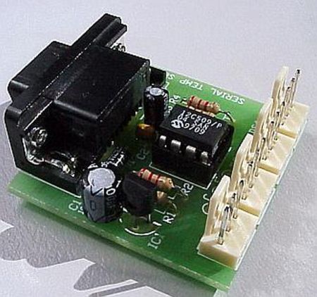
Just a handful of components builds an 8-pin microcontroller based circuit for temperature logging via a serial port; small, fast, and acceptably accurate.

Temperature Sensor

Features

  • provides real-time data to your computer via serial port,
  • interfaces up to four DS1820 temperature sensors,
  • absolute accuracy near 0.5 degrees celcius (as per DS1820 specifications),
  • relative accuracy near 0.01 degrees celcius,
  • speaks in Centigrade or Fahrenheit (selectable by header pins),
  • powered by your computer’s serial port, no extra supply to organise,
  • data format easily processed, no special programs required,
  • minimal parts count reduces cost,
  • built-in serial number for circuit identification,
  • special versions available for exotic requirements; high speed, low speed, additional sensors, long distance or pedantic serial bus.
  • spare inputs can be used as single-bit digital inputs, (feature removed from final version but can be re-inserted),

Applications

A few ideas of how this circuit can be used:

  • simple weather reports for web pages,
  • computer power supply temperature warnings,
  • redundant critical systems monitoring,
  • house temperature monitoring,
  • complex home automation tasks (start fan if warmer outside during winter),
  • refrigerator testing,
  • brewing temperature regulation,
  • fish tank heater verification,
  • microclimate logging (ground versus air temperature),
  • daylight sensing (LDR on digital input),
  • primitive locking (using serial number),
  • remote monitoring of emu fat in a freezer truck,

Availability

The electronics kit maker Kitsrushas released a PCB and kit of this design. Other kit sellers also sell the kit. Here is a summary:


Country Organisation Item Number GPL Compliance Date Checked
Australia Ozitronics K145 Complete 13th June 2003
United States of America Carl’s Electronics Inc CK110 Partial 13th June 2003
Kingston, Ontario, Canada QKits QK145 Complete 13th June 2003
Hong Kong Kitsrus K145 Complete 13th June 2003
Denmark eekit.dk 0104-K145 Partial 29th November 2004

(If you also sell this kit, and you would like to be added to the list, please write to me, including your country, organisation name, links to your web site and to the kit page. There is no reciprocal link condition. You may be asked to provide a link to this page, but that is for compliance with the software license.)


Theory of Operation
The program in the microcontroller knows two protocols; the one wire bus used by the DS1820 temperature sensor, and the serial protocol expected by your computer. Once power is applied, the program fetches data from the sensors and sends it to the serial port, repeatedly.


The data from the DS1820 arrives in a format peculiar to the sensor. The program calculates the temperature from the data and translates it into human readable ASCII digits. No special program is required on the computer.


Usage Instructions
Plug the circuit into the serial port of a computer. Persuade the computer to expect serial data at 2400 baud, 8 bits, no parity, one or two stop bits. Ask the computer to raise the DTR signal. (See below for software that will do this for you.) The microcontroller will start talking to the connected DS1820 sensors and the circuit should begin transmitting data to the computer. For example:


For more detail: Quozl’s Temperature Sensor Project using PIC12C509

The post Quozl’s Temperature Sensor Project using PIC12C509 appeared first on PIC Microcontroller.


A brief overview of Allegro ACS712 current sensor. Part 2 – Interface the sensor with a PIC microcontroller

$
0
0

In the first part of this discussion, the features of ACS712 device were briefly discussed. Now we will use that theory to implement the ACS712 sensor to make a simple DC current meter. The analog output voltage from the sensor is measured through an ADC channel of the PIC16F1847 microcontroller. A voltage to current conversion equation will be derived and implemented in the firmware of the PIC microcontroller and the actual load current will be displayed on a character LCD.

Experimental circuit setup

We are going to setup a test experiment to demonstrate the use of ACS712 to measure a DC current. I am using an ACS712-05B breakout module (you can find them cheap on ebay) for this purpose.

A brief overview of Allegro ACS712 current sensor. Part 2 - Interface the sensor with a PIC microcontrollerIt has got a 1 nF filter capacitor connected between pin 6 and ground, a 100 nF decoupling capacitor between power supply lines, and a power on LED soldered on the board. The power supply and output lines are accessible through header pins on one side, whereas, the current terminals are connected to a 2-pin terminal block on the opposite side, as shown below.

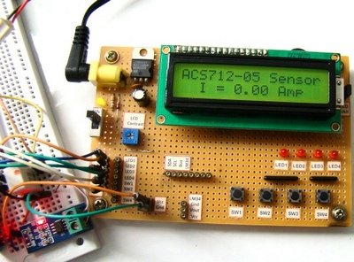
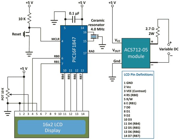
The experimental circuit diagram of the DC current meter is shown below. A 2.7 Ω (rated 2 Watt) resistor is connected in series with the current terminals and a varying dc voltage is applied to vary the current through the resistor and the current path. The output of the sensor module goes to AN0 (pin 17) ADC channel of the PIC16F1847 microcontroller. A 16×2 character LCD is used to display the measured current output.

I am using my PIC16F1847 breadboard module along with the Experimenter’s I/O board to demonstrate this experiment.

The microcontroller uses the supply voltage (+5V) as reference for A/D conversion. The digitized sensor output is processed through software to convert it to the actual current value. The mathematics involved in the process is described in the white board below.

For Vcc=5V and ADC Vref=5V, the relationship between output voltage and ADC Count is

But,

Important note: The calculations shown above considered supply voltage Vcc = Vref = 5.0 V. Interestingly, the final equation relating I and Count remains the same even the power supply fluctuates. For example, suppose Vcc fluctuates and becomes 4.0 V. Then, the sensitivity of the ACS712-05B also changes to 0.185 x 4/5 = 0.148 mV.

A brief overview of Allegro ACS712 current sensor. Part 2 - Interface the sensor with a PIC microcontroller SchematicIf you repeat the above calculations with Vcc = Vref = 4.0 V and sensitivity = 0.148 mV, you will end up with the same equation for I and Count. This was possible because of the ratiometric output of the ACS712 sensor.

The equation clearly tells that the current resolution for this setup is 26.4 mA, which corresponds to count 513, one count higher than the zero current offset. Therefore, this kind of arrangement is not suitable for measuring low current. You need an external Op-Amp circuit to enhance the resolution and be able to make more sensitive current measurement. If you are interested on that, you can visit Sparkfun’s ACS712 Low Current Sensor Breakout page that provides a circuit diagram for such an arrangement.


For more detail: A brief overview of Allegro ACS712 current sensor. Part 2 – Interface the sensor with a PIC microcontroller

The post A brief overview of Allegro ACS712 current sensor. Part 2 – Interface the sensor with a PIC microcontroller appeared first on PIC Microcontroller.

Bosch launches smallest high performance barometric pressure sensor at CES 2017

$
0
0

image001_img_w630

The BMP380 is aimed at the growing markets of gaming, sports and health management, as well as indoor and outdoor navigation. By measuring barometric pressure, the sensor enables drones, smartphones, tablets, wearables and other mobile devices to accurately determine altitude changes, in both indoor and outdoor environments.

Wide range of applications

This new BMP380 sensor offers outstanding design flexibility, providing a single package solution that can be easily integrated into a multitude of existing and upcoming applications and devices.

Typical applications for the BMP380 include altitude stabilization in drones, where altitude information is utilized to improve flight stability and landing accuracy. This simplifies drone steering, thereby making drones attractive for a broader range of users. The BMP380 can also substantially improve calorie expenditure measurement accuracy in wearables and mobile devices, for example by identifying whether a person is walking upstairs or downstairs in a step tracking application. Especially in hilly environments, this allows runners and cyclists to significantly improve the monitoring accuracy of their performance. In smartphones, tablets and wearables, this sensor brings unprecedented precision to outdoor/indoor navigation and localization applications, i.e. by utilizing altitude data to determine the user’s floor level in a building, and enhancing GPS accuracy outdoors.

Accurate and unmatched ease of use

Pressure and temperature data can be stored in the built-in FIFO of 512 byte. The new FIFO and interrupt functionality provide simple access to data and storage. This greatly improves ease of use while helping to reduce power consumption to only 2.0µA at 1Hz during full operation.

for more detail: Bosch launches smallest high performance barometric pressure sensor at CES 2017

The post Bosch launches smallest high performance barometric pressure sensor at CES 2017 appeared first on PIC Microcontroller.

INCREASING BATTERY LIFE WITH UB20M VOLTAGE DETECTOR

$
0
0

Engineers at the University of Bristol have developed a three terminal pico-power chip that can cut standby drain in sensor nodes – even compared with today’s low-power microcontrollers.

It does this by replacing the low duty-cycle sleep-wake-sleep pattern used on MCU-based sensor monitors, with ‘off’. A voltage detector powered by the sensor – there is no other power source –  starts the processor when the sensor produces a voltage

diagram

At 5pA (20°C 1V), power draw from the sensor through the input/supply pin is so low that the chip can directly interface with high-impedance sensors such as antennas, piezo-electric accelerometers, or photodiodes. With so little current required, the chip does not collapse the sensor voltage.

“It will work from five infra-red diodes in series, powered from a TV remote control 5m away, or an un-powered accelerometer”, Bristol engineer Bernard Stark told Electronics Weekly.

Called UB20M, the only power it draws from the system is 100pA(max) leakage through its open drain output transistor. Input threshold is set at 0.6V.

Once the sensor presents greater than 0.6V to the input, the output FET turns on (RDSon~800Ω), and its low resistance can either be used to turn on a p-FET to power up a microcontroller, or can wake a microcontroller from sleep.


for more detail:  INCREASING BATTERY LIFE WITH UB20M VOLTAGE DETECTOR

The post INCREASING BATTERY LIFE WITH UB20M VOLTAGE DETECTOR appeared first on PIC Microcontroller.

Environmental Sensors

$
0
0

sensirion-environmental-sensing-infographic-88b21


Environmental conditions have a major impact on our well-being, comfort, and productivity. Sensirion’s sensor solutions provide detailed and reliable data on key environmental parameters such as humidity, temperature, volatile organic compounds (VOCs), particulate matter (PM2.5), and CO2. Environmental Sensing opens up new possibilities to create smarter devices that improve our comfort and well-being as well as increase energy efficiency in a wide variety of applications.

Product Highlight

Multi-Pixel Gas Sensor

The digital gas sensor SGP opens up new possibilities for the measurement of indoor air quality. The long-term stable metal-oxide gas sensor features multiple sensing elements on one chip, the SGP provides in-depth information on air quality. The sensing element features an unmatched robustness against contaminating gases present in real-world applications, enabling a unique long-term stability and low drift. The small package size (2.45 x 2.45 x 0.9 mm3 DFN), the I2C interface, and the dust and water protection membrane make the SGP easy to integrate into a  large variety of applications, e.g. in appliances or smart home devices.

for more detail:  Environmental Sensors

The post Environmental Sensors appeared first on PIC Microcontroller.

Smallest seismic sensor uses vibration spectral analysis

$
0
0

170418eedn_omron_seismic_sensor

Omron Electronic Components believes it has the world’s smallest class size seismic sensor, specifically designed to trigger the shutdown of potentially hazardous or easily damaged systems in the event of an earthquake.

Specifically designed for the growing number of autonomous IoT systems, the Omron D7S provides high precision measurement of spectral intensity, allowing it to reject impulse vibration noise and only respond to genuine seismic activity. D7S features its own internal memory and I ²C interface, allowing it to be readily integrated into IoT devices. Potential applications include smart electricity and gas meters, wireless sensors, industrial control panels, electricity distribution panels, fire-prevention systems, home appliances such as heaters and gas stoves, chemical plants, expressways, bridges, tunnels, roads and many more.

Omron adds, “Earthquakes are extremely common around the world. On average, 50 earthquakes strike each day, or about 20,000 a year. Many are weak enough to go unnoticed but some are catastrophic….designers can make systems safer and minimise the risk of secondary damage after earthquakes by safely shutting off and stopping hazardous devices. The sensor can also help determine damage by mapping seismic intensity and providing building collapse information.”

for more detail : Smallest seismic sensor uses vibration spectral analysis

Current Project / Post can also be found using:

  • led spectrum analyzer schematics

The post Smallest seismic sensor uses vibration spectral analysis appeared first on PIC Microcontroller.

Viewing all 406 articles
Browse latest View live


Latest Images

<script src="https://jsc.adskeeper.com/r/s/rssing.com.1596347.js" async> </script>