Quantcast
Channel: sensor | Battery Guide
Viewing all 406 articles
Browse latest View live

AMS uses 3D chip technology for smartphone sensors

$
0
0

Description

The AS3721 is a compact System PMU supporting up to 20 high current rails. The device offers advanced power management functions. All necessary ICs and peripherals in a battery powered mobilde device are supplied by the AS3721. It features 4 DCDC buck converters as well as 12 low noise LDOs. The different regulated supply voltages are programmable via the serial control interface. 3-4MHz operating with 1 uH coils is reducing cost and PCB space.

AS3721 further features 3 DCDC buck controller which are ideal to support processor currents ranging from 5A up to 20A. The multi-phase topology operating on 3MHz ensures fast load transient responses and reduces the footprint for external components.

The single supply voltage may vary from 2.7V to 5.5V.

Key Features

  • 4 DCDC step down regulators (3-4 MHz)
  • 3 DCDC step down controller
  • 12 universal LDOs
  • RTC
  • Supervisor with interrupt generation and selectable warning levels
  • General Purpose IOs
  • ADC with intern and external sources
  • OTP programmable Boot and Power-down sequence
  • Stand-by function with programmable sequence and voltages
  • Control Interface
  • Package:124-pin CTBGA (8x8mm), 0.5mm pitch

Applications

The device is suitable for Tablet PCs, NetBooks, portable media players, portable navigation devices, and mobile internet devices.

AMS uses 3D chip technology for smartphone sensors

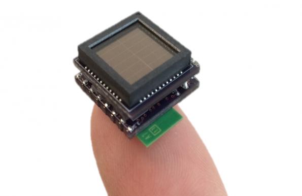
Austrian chip maker ams is applying through-silicon via (TSV) 3D IC fabrication technology to its ambient light sensor devices.

TSV technology is being used to interconnect stacked wafers in FPGAs and memory chips and ams believes it can apply the technology to analogue sensors to very small wafer scale packages.

“We have been developing the TSV capability and expect to be in production with first sensors in the middle of the year,” said Thomas Riener, senior v-p marketing communications at ams.

The company is planning to develop more highly integrated and smaller ambient light sensors for use in smartphones and cameras.

After the acquisition of US-based light sensor firm TAOS in 2011, supplying sensors to smartphone manufacturers has become an important business for the Graz-based manufacturer.

“We have 40% market share in ambient light sensors in smartphones, “claimed Riener.

As a result the firm has doubled revenues in the last three years and sensor devices, standard products and Asics, make up 70% of sales for ams.

The mixed-signal company has also developed NFC and RFID “signal booster” devices for use in smartphones.

“These will be revenue driver this year and beyond, we already have a high number of design-ins,” said Riener.

The company also supplies an interface chip to MEMS microphone supplier Knowles. “

The company designs chip in the US and Europe, but all manufacturing is in Austria.

“Manufacturing is very important for us and we believe in retaining all critical production technologies,” said Riener.

“We believe analogue chip production is critical to Europe and the engineering talent is here,” said Riener.

Also important to ams is a new power management IC (PMIC) it originally designed as an Asic for Nvidia for its Tegra smartphone processor.


For more read: AMS uses 3D chip technology for smartphone sensors

The post AMS uses 3D chip technology for smartphone sensors appeared first on PIC Microcontroller.


MOTION SENSOR USING PIR SENSOR MODULE WITH PIC MICROCONTROLLER AND WITHOUT MICROCONTROLLER

$
0
0
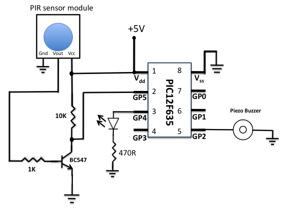
The circuit diagram is quite simple. I have powered my circuit with 4 AA batteries that gives 6 V supply.
A diode is used in series to drop the voltage down to 5.4 V as the operating voltage for the PIC microcontroller should be below 5.5 V. Besides, the diode also provides the protection to the circuit in case of reverse polarity of the power supply. I have tested the circuit with NI-MH rechargeable batteries (that gives 4.8 V) and it worked, but I recommend to use the alkaline batteries (1.5 V each) for better performance. You can also use a 9 V battery but then you need a LM7805 regulator IC in your circuit.
 MOTION SENSOR USING PIR SENSOR MODULE WITH PIC MICROCONTROLLER AND WITHOUT MICROCONTROLLER The output of the PIR sensor module is monitored through GP5 (pin 2) of PIC12F635. When the motion is sensed, this output is high at about 3.3 V (my sensor module has a 3.3V regulator IC on board). You could still use this voltage as a valid logic high for PIC12F635, but I preferred to use this voltage to drive the base of an NPN transistor (BC547) so that at the collector we will have the full swing of the logic voltages. Now, the microcontroller monitors the voltage at the collector of the transistor. During the normal condition, the transistor is cut off, and the collector output is at logic high (+5 V). When the motion is sensed, the high output from the sensor module saturates the transistor and the voltage at the collector drops down to logic low. The jumper selection for trigger is at H position, so the sensor output will remain active as long as the motion exists. Note that the PIC12F635 microcontroller uses the internal clock oscillator at 4.0 MHz. The MCLR function is disabled and WDT is OFF in this project.
 MOTION SENSOR USING PIR SENSOR MODULE WITH PIC MICROCONTROLLER AND WITHOUT MICROCONTROLLER  Schematic
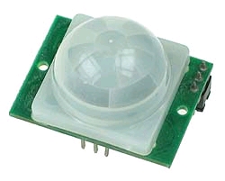
Pyroelectric sensor module,developed for human body detection. A PIR detector combined with a fresnel lens are mounted on a compact size PCB together with an analog IC (SB0061) and limited components to form the module. High level output (3.3V) of pre-settable variable width (5Secs -18 Minutes) is provided.

Current Project / Post can also be found using:

  • mini projects in sensors and transducers
  • project for tranducer

The post MOTION SENSOR USING PIR SENSOR MODULE WITH PIC MICROCONTROLLER AND WITHOUT MICROCONTROLLER appeared first on PIC Microcontroller.

Lightning detector on a chip

$
0
0

Description

The AS3935 is a programmable Lightning Sensor IC that detects the presence and approach of potentially hazardous lightning activity in the vicinity.  It detects intra-cloud activity as well as cloud to ground flashes, often enabling risk to be evaluated for approaching storms. The US National Weather Bureau suggests the 30-30 rule when lightning is imminent (When a flash is seen and the thunder is heard less than 30 seconds later, the storm is within 10 km. Head immediately for a safe shelter. Stay in the shelter for 30 minutes after the last sound of thunder you hear).

Key Features

  • Franklin Lightning Sensor provides early warning indication of lightning storm activity within a 40km range
  • Provides distance estimation to the head of the storm
  • Detects both cloud-to-ground and intra-cloud (cloud-to-cloud) flashes
  • Intelligent algorithm provides for false disturber rejection
  • Programmable detection levels enable threshold setting for optimal configurability
  • SPI and I2C interface is used for control and register reading
  • Automatic Antenna Tuning
  • Supply voltage range 2.4 to 5.5V
  • Power-down, listening and active modes
  • Temperature range: -40°C to 85°C

Lightning detector on a chip

Austriamicrosystems has introduced a lightning sensor IC with an RF receiver that detects the electrical emissions from lightning activity.

The device could be used in portable lightning sensors which could become consumer safety products.

Using an algorithm developed by the firm in the AS3935 then converts the RF signal into an estimation of the distance to the head of the storm.

“The algorithm, which draws on extensive meteorological survey data, produces an estimated distance-to-storm calculation from 40km down to 1km, while rejecting disturbances from man-made signals such as motors and microwave ovens,” said the supplier.

Dubbed the Franklin Lightning Sensor, it has low power operation with a current consumption of 60µA and is packages in a 4mm x 4mm 16-pin MLPQ package.

A typical application for the AS3935 requires only a simple microcontroller with a SPI or I2C interface and seven other passive components allowing it to fit easily in a space about the size of an automobile keychain remote.

www.austriamicrosystems.com/Lighning-Sensor/AS3935


For more read:  Lightning detector on a chip

The post Lightning detector on a chip appeared first on PIC Microcontroller.

Quozl’s Temperature Sensor Project using PIC12C509

$
0
0

Introduction

Just a handful of components builds an 8-pin microcontroller based circuit for temperature logging via a serial port; small, fast, and acceptably accurate.

Temperature Sensor

Features

  • provides real-time data to your computer via serial port,
  • interfaces up to four DS1820 temperature sensors,
  • absolute accuracy near 0.5 degrees celcius (as per DS1820 specifications),
  • relative accuracy near 0.01 degrees celcius,
  • speaks in Centigrade or Fahrenheit (selectable by header pins),
  • powered by your computer’s serial port, no extra supply to organise,
  • data format easily processed, no special programs required,
  • minimal parts count reduces cost,
  • built-in serial number for circuit identification,
  • special versions available for exotic requirements; high speed, low speed, additional sensors, long distance or pedantic serial bus.
  • spare inputs can be used as single-bit digital inputs, (feature removed from final version but can be re-inserted),

Applications

A few ideas of how this circuit can be used:

  • simple weather reports for web pages,
  • computer power supply temperature warnings,
  • redundant critical systems monitoring,
  • house temperature monitoring,
  • complex home automation tasks (start fan if warmer outside during winter),
  • refrigerator testing,
  • brewing temperature regulation,
  • fish tank heater verification,
  • microclimate logging (ground versus air temperature),
  • daylight sensing (LDR on digital input),
  • primitive locking (using serial number),
  • remote monitoring of emu fat in a freezer truck,

Availability

The electronics kit maker Kitsrushas released a PCB and kit of this design. Other kit sellers also sell the kit. Here is a summary:


Country Organisation Item Number GPL Compliance Date Checked
Australia Ozitronics K145 Complete 13th June 2003
United States of America Carl’s Electronics Inc CK110 Partial 13th June 2003
Kingston, Ontario, Canada QKits QK145 Complete 13th June 2003
Hong Kong Kitsrus K145 Complete 13th June 2003
Denmark eekit.dk 0104-K145 Partial 29th November 2004

(If you also sell this kit, and you would like to be added to the list, please write to me, including your country, organisation name, links to your web site and to the kit page. There is no reciprocal link condition. You may be asked to provide a link to this page, but that is for compliance with the software license.)


Theory of Operation
The program in the microcontroller knows two protocols; the one wire bus used by the DS1820 temperature sensor, and the serial protocol expected by your computer. Once power is applied, the program fetches data from the sensors and sends it to the serial port, repeatedly.


The data from the DS1820 arrives in a format peculiar to the sensor. The program calculates the temperature from the data and translates it into human readable ASCII digits. No special program is required on the computer.


Usage Instructions
Plug the circuit into the serial port of a computer. Persuade the computer to expect serial data at 2400 baud, 8 bits, no parity, one or two stop bits. Ask the computer to raise the DTR signal. (See below for software that will do this for you.) The microcontroller will start talking to the connected DS1820 sensors and the circuit should begin transmitting data to the computer. For example:


For more detail: Quozl’s Temperature Sensor Project using PIC12C509

Current Project / Post can also be found using:

  • mini projects using transducer
  • www temperature measurement using microcontroller with c program and pdf com
  • how to detect metal without contact using pic16f877a
  • introduction of water trmperaturr display project

The post Quozl’s Temperature Sensor Project using PIC12C509 appeared first on PIC Microcontroller.

Interfacing LM35 Temperature Sensor with PIC Microcontroller.

$
0
0

The are many cool sensors available now a days, ranging from IR distance sensor modules, accelerometers, humidity sensors, temperature sensors and many many more(gas sensors, alcohol sensor, motion sensors, touch screens). Many of these are analog in nature. That means they give a voltage output that varies directly (and linearly) with the sensed quantity. For example in LM35 temperature sensor, the output voltage is 10mV per degree centigrade. That means if output is 300mV then the temperature is 30 degrees. In this tutorial we will learn how to interface LM35 temperature sensor with PIC18F4520 microcontroller and display its output on the LCD module.

Interfacing LM35 Temperature Sensor with PIC MicrocontrollerFirst I recommend you to go and read the following tutorial as they are the base of this small project.

After reading the ADC tutorial given above you will note the the PIC MCU’s ADC gives us the value between 0-1023 for input voltage of 0 to 5v provided it is configured exactly as in the above tutorial. So if the reading is 0 then input is 0v, if reading is 1023 then input is 5v. So in general form if the adc read out is val then voltage is.

unsigned int val;
val=ADCRead(0); //Read Channel 0
voltage= ((val)/1023.0)*5;

The above formula give voltage in Volts, to get Voltage in mili Volts (mV) we must multiply it with 1000, so

voltage=((val)/1023.0)*5*1000); //Voltage is in mV

since 10mV = 1 degree, to get temperature we must divide it by 10, so

t=((val)/1023.0)*5*100); //t is in degree centigrade

simplifying further we get

t=((val/1023.0)*500);
t=(val*0.48876);

we round off this value, so

t=round(val*0.48876);

remember round() is a standard c library function

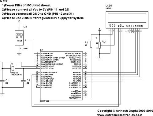
Interfacing LM35 Temperature Sensor with PIC Microcontroller schematicHardware for LM35 based thermometer.

You will need a PIC18F4520 chip running at 20MHz attached with a standard 16×2 LCD Module and LM35 on AN0 pin. LM35 is a 3 pin device as show below.

connect the +Vs Pin to 5v and GND to GND. The output must be connected to the analog input pin 0 of the PIC18F4520 MCU. It is labeled AN0 in the datasheet. It is pin number 2 on the 40 pin package. It is also called RA0 because it is shared with PORTA0.

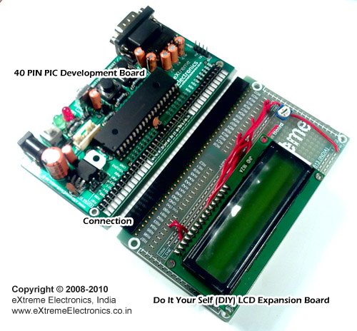
We will use our 40 PIN PIC Development board to realize the project. The base board has all the basic circuit to run the PIC. The extra part required for this project like LCD and the LM35 temperature sensor are installed in the expansion board.


For more detail: Interfacing LM35 Temperature Sensor with PIC Microcontroller.

Current Project / Post can also be found using:

  • Circuit for fire fighting robot using pic mcro 16f887a
  • transducer pic
  • interfacing LM35 with pic microcontroller chip
  • pic programming for robot

The post Interfacing LM35 Temperature Sensor with PIC Microcontroller. appeared first on PIC Microcontroller.

A brief overview of Allegro ACS712 current sensor. Part 2 – Interface the sensor with a PIC microcontroller

$
0
0

In the first part of this discussion, the features of ACS712 device were briefly discussed. Now we will use that theory to implement the ACS712 sensor to make a simple DC current meter. The analog output voltage from the sensor is measured through an ADC channel of the PIC16F1847 microcontroller. A voltage to current conversion equation will be derived and implemented in the firmware of the PIC microcontroller and the actual load current will be displayed on a character LCD.

Experimental circuit setup

We are going to setup a test experiment to demonstrate the use of ACS712 to measure a DC current. I am using an ACS712-05B breakout module (you can find them cheap on ebay) for this purpose.

A brief overview of Allegro ACS712 current sensor. Part 2 - Interface the sensor with a PIC microcontrollerIt has got a 1 nF filter capacitor connected between pin 6 and ground, a 100 nF decoupling capacitor between power supply lines, and a power on LED soldered on the board. The power supply and output lines are accessible through header pins on one side, whereas, the current terminals are connected to a 2-pin terminal block on the opposite side, as shown below.

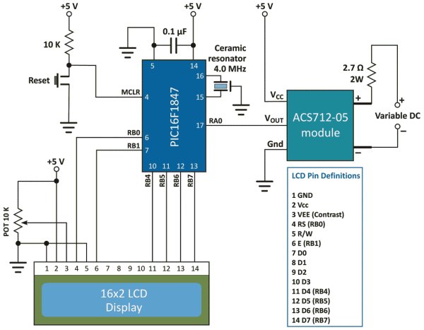
The experimental circuit diagram of the DC current meter is shown below. A 2.7 Ω (rated 2 Watt) resistor is connected in series with the current terminals and a varying dc voltage is applied to vary the current through the resistor and the current path. The output of the sensor module goes to AN0 (pin 17) ADC channel of the PIC16F1847 microcontroller. A 16×2 character LCD is used to display the measured current output.

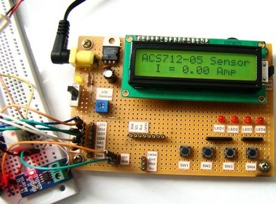
I am using my PIC16F1847 breadboard module along with the Experimenter’s I/O board to demonstrate this experiment.

The microcontroller uses the supply voltage (+5V) as reference for A/D conversion. The digitized sensor output is processed through software to convert it to the actual current value. The mathematics involved in the process is described in the white board below.

For Vcc=5V and ADC Vref=5V, the relationship between output voltage and ADC Count is

But,

Important note: The calculations shown above considered supply voltage Vcc = Vref = 5.0 V. Interestingly, the final equation relating I and Count remains the same even the power supply fluctuates. For example, suppose Vcc fluctuates and becomes 4.0 V. Then, the sensitivity of the ACS712-05B also changes to 0.185 x 4/5 = 0.148 mV.

A brief overview of Allegro ACS712 current sensor. Part 2 - Interface the sensor with a PIC microcontroller SchematicIf you repeat the above calculations with Vcc = Vref = 4.0 V and sensitivity = 0.148 mV, you will end up with the same equation for I and Count. This was possible because of the ratiometric output of the ACS712 sensor.

The equation clearly tells that the current resolution for this setup is 26.4 mA, which corresponds to count 513, one count higher than the zero current offset. Therefore, this kind of arrangement is not suitable for measuring low current. You need an external Op-Amp circuit to enhance the resolution and be able to make more sensitive current measurement. If you are interested on that, you can visit Sparkfun’s ACS712 Low Current Sensor Breakout page that provides a circuit diagram for such an arrangement.


For more detail: A brief overview of Allegro ACS712 current sensor. Part 2 – Interface the sensor with a PIC microcontroller

The post A brief overview of Allegro ACS712 current sensor. Part 2 – Interface the sensor with a PIC microcontroller appeared first on PIC Microcontroller.

Interfacing Temperature Sensor with Microchip PIC16F876A

$
0
0

The tutorial aims at providing the necessary information for interfacing an analog type temperature sensor with a Microchip PIC Microcontroller. PIC (Peripheral Interface Controllers) was introduced in 1985. The PIC16F876A has 8K of Flash Program Memory, 368 bytes of Data Memory (RAM) and many other attractive features. Some features are ADC, USART, and 14 Interrupts all in 28 PDIP Package.

mperature Sensor with Microchip PIC16F876AThe Analog temperature sensor used is LM35. It has a transfer function of 10mv/’c. The output of LM35 is analog voltage which varies with changes in temperature. This analog voltage is digitized using the On-Chip 10bit A/D Converter and the value is displayed on a 2×16 LCD.

It is possible to switch On/Off an external application based on temperature value.

The LCD is based on HD44780 controller. The programming has been done using the MikroC compiler from Mikroelektronika (www.mikroe.com). The demo version has a 2KB Hex Output limit, fortunately it is more than enough for our requirement.

Program

int t1,temp;

char *text[6];

void main()

{adcon1=14;

lcd_init(&portb);

lcd_out(1,1,”Temperature”);

lcd_out(2,8,”‘C”);

while(1)

{t1=adc_read(0);

//temp=0.245*t1;          // For TMP37 Sensor 20mv/’c

temp=0.245*t1*2;        // For Lm35 Sensor 10mv/’c

inttostr(temp,text);

lcd_cmd(lcd_cursor_off);

lcd_out(2,1,text);

delay_ms(100);}}

Interfacing Temperature Sensor with Microchip PIC16F876A SchematicThe program is self explanatory, however let me explain you the calculation done. In a while loop. The Input channel 0 is read and the digitized value is obtained. Now the smallest digitized value is equal to Vref/((2^10)-1). Internal Vref is 4096mV but we will consider 5000mV for the ease of calculation. Multiplying the value obtained above with the digitized value will give us the analog voltage. Since the transfer function of Lm35 is 10mV/’c, we can obtain the temperature.


For more detail: Interfacing Temperature Sensor with Microchip PIC16F876A

The post Interfacing Temperature Sensor with Microchip PIC16F876A appeared first on PIC Microcontroller.

DIY Muscle Sensor / EMG Circuit for a Microcontroller

$
0
0

Measuring muscle activation via electric potential, referred to as electromyography (EMG) , has traditionally been used for medical research and diagnosis of neuromuscular disorders. However, with the advent of ever shrinking yet more powerful microcontrollers and integrated circuits, EMG circuits and sensors have found their way into prosthetics, robotics and other control systems. Yet, EMG systems remain expensive and mostly outside the grasp of modern hobbyist.

This instructable will teach you how to make your own muscle sensor / EMG circuit to incorporate into your next project. Use it to control video games, robot arms, exoskeletons, etc.

Click on the video below for a demonstrations on how to hook up and use your EMG circuit board!
You can now also purchase  EMG sensors, kits, cables and electrodes at www.AdvancerTechnologies.com!
Muscle Sensor Kit (now also on SparkFun)

Muscle Sensor Electrodes
Note: This sensor is not intended for use in the diagnosis of disease or other conditions, or in the cure, mitigation treatment, or prevention of disease, in a man or other animals.

DIY Muscle Sensor EMG Circuit for a MicrocontrollerAbout Advancer Technologies 
Advancer Technologies is a company devoted to developing innovative game-changing biomedical and biomechanical technologies and applied sciences. Additionally, Advancer Technologies promotes all forms of interest and learning into biomedical technologies. To help culture and educate future great minds and concepts in the field, they frequently post informative instructions on some of their technologies. For more information, please visit www.AdvancerTechnologies.com .

Step 1: Materials

Click on the links to go to where you can buy items/order free samples.
Circuit Chips

3x TL072 IC Chip  – Free Samples
1x INA106 IC Chip  – Free Samples

Cables and Electrodes
1x EMG Cables   (set of 3)… Note: you could optionally connect the alligator clips directly to the electrodes.
3x EMG Electrodes

Power
2x 9V Battery
2x 9V battery clips

Capacitors
• 2x 1.0 uF Tant 
• 1x 0.01 uF Ceramic Disc
• 1x 1.0 uF Ceramic Disc  

Resistors
• 3x 150 kOhm 1%  
• 2x 1 MOhm 1% 
• 2x 80.6 kOhm 1%
• 6x 10 kOhm 1%
• 1x 100 kOhm Trimmer 
• 1x 1 kOhm 1%

Misc
• 2x 1N4148 Diode
Jumper wires
• 3x Alligator clip cables

Optional
• 1x Oscilloscope
• 1x Multimeter

Step 2: POWER SUPPLY

To start things off, you’ll need both a positive and negative voltage power supply. We will make these using two 9V batteries.
Now, everyone knows what a positive voltage power supply is, (e.g. common battery) but how do you go about making a negative voltage power supply?
Common electrical circuit rule of thumb is when you connect two batteries in series (eg positive terminal of battery 1 connected to the negative terminal of battery 2) then measure the voltage from the negative terminal of battery 1 and the positive terminal of battery 2, the measured voltage is equal to the summation of the voltages of battery 1 and battery 2.
For this circuit we want a +9V and a -9V power supplies. If we connect our two 9V batteries in series, we will get a power supply of +18V. So how do we get the -9V from these two?
It might help to think about what voltage actually means… voltage is an electrical potential difference. The keyword here is difference. Voltages are only meaningful in terms of the reference point (or more commonly referred to as ground).

A voltage is the electrical potential between this reference point and the point you are measuring. Do you see the answer yet?
We do indeed get a +18V voltage reading if we use battery 1’s negative terminal as the reference point… but what if we choose the connection between battery 1’s positive terminal and battery 2’s negative terminal? If we use this point as our reference or ground, then battery 2’s positive terminals voltage will be +9V and battery 1’s negative terminal will be -9V!
Using your breadboard, 9V batteries and battery clips, connect the battery clip wires as shown. However, for the time being, disconnect the positive terminal of battery 2 and the negative terminal of battery 1. It is good practice to always disconnect your power while you assemble a circuit. At the end of the assembly we will reconnect these wires to power the circuit on. (You could also add switches to do this)

Step 3: SIGNAL ACQUISITION

Next, we will work on the signal acquisition phase of your EMG circuit which we will use to measure your body’s nervous system’s electrical impulses used to activate muscle fibers.
First, get out your INA106 IC chip (chip A) and insert it into your breadboard as illustrated above. The INA106 is a difference amplifier which will measure and amplify (G=110) the very small voltage differences between the two electrodes you place on your muscle.
Next, grab two 1 M ohm resistors, bend them and then plug them in to your breadboard like the two examples shown. One should connect pins 5 and 6 and the other should bridge pin 1 to your ground rail of your board.
Don’t worry about the other pins of the INA106 for now; we’ll come back to those later.

DIY Muscle Sensor EMG Circuit for a Microcontroller SchematicStep 4: SIGNAL CONDITIONING – Amplification

In this phase, we’re going to take those very small signals measured in the SIGNAL ACQUISITION phase and amplify them.
Let’s start first with two series of amplification; the first will be inverting amplifier with a gain of -15. An inverting amplifier does exactly what it sounds like. It amplifies your signal but also inverts it. You can find more info about inverting amplifiers here .
We are going to first build an inverting amplifier with a gain of -15. To do this, we’ll need one of the TL072 chips (chip B), one 150 kOhm resistor and a 10 kOhm resistor.
Place chip B as the picture indicates. Now use a jumper wire and connect pin 6 of chip A two rows past pin 8 of chip A. Grab one of the 10 kOhm resistors and plug one pin into this row as well. Connect the other pin to pin 6 of chip B. Bend a 150 kOhm resistor and connect one pin to chip B’s pin 6 and the other to pin 7. You can calculate the gain by G=-R2/R1 or in this case G=-150 kOhm / 10 kOhm. (See image 1)

Next, we are going to add a capacitor to AC couple the signal. AC coupling is useful in removing DC error offset in a signal. Read more about AC and DC coupling here .
Continuing on, we are going to add an active high pass filter to get rid of any DC offset and low frequency noise. To do this you will need two 150 kOhm resistors and a 0.01uF capacitor. Use a jumper wire and the 0.01 uF capacitor to bridge the center gab of your breadboard as shown. (One end of the jumper wire should be connected to pin 7 of chip B). The 150 kOhm resistor will connect the capacitor you just placed to pin 2 of chip B. Now, bend the 150 kOhm resistor and push it into connect pins 1 & 2. (See image 2)
Also, go ahead and connect chip B’s pin 4 to your -9V rail, pin 8 to your +9V rail, and pins 3 & 5 to your GND rail.


For more detail: DIY Muscle Sensor / EMG Circuit for a Microcontroller

Current Project / Post can also be found using:

  • pic baded robit car
  • pic based robots
  • Pic microcontroller programming for robotics
  • robot making using PIC

The post DIY Muscle Sensor / EMG Circuit for a Microcontroller appeared first on PIC Microcontroller.

Digital Temperature Sensor Circuit

$
0
0
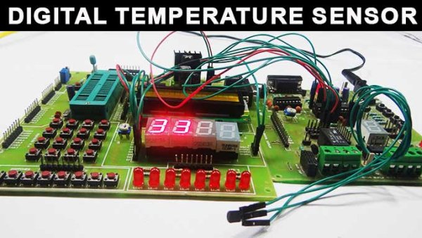
Temperature sensors are widely used in electronic equipments to display the temperature. You can see the digital clock displaying the room temperature value. It is due to the temperature sensor embedded in it. Generally, temperature value is analog. It is converted to digital value and then it is displayed. This article describes the same converting analog value to a digital value.Digital Temperature Sensor Circuit

Digital Temperature Sensor Circuit Principle:

The main principle of this circuit is to display the digital temperature value. Here, ATmega8 microcontroller is used. The ATmega8 has inbuilt analog to digital converter with six multiplexed channels. This reduces interfacing of external analog to digital converter IC. The analog temperature value is directly applied to input ADC channels of microcontroller. Successive approximation method is used for Analog to digital conversion internally.

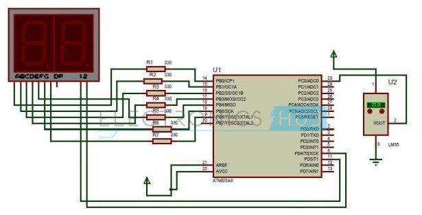
Digital Temperature Sensor Circuit Diagram:

Circuit Components:
  • Resistors – R1 to R7 having the value of 330 Ohms each.
  • LM35 Temperature sensor
  • ATmega8 Microcontroller
  • 7 Segment Display

Digital Temperature Sensor Circuit Design:

The digital temperature circuit consists of ATmega8 microcontroller, LM35 temperature sensor, 7 segment display. The temperature sensor Lm35 is connected to one of the ADC channels of microcontroller.Digital Temperature Sensor Circuit schematic
ATmega8 has six ADC channels at Port C. PC0-PC5 pins of Atmega8 act as ADC channels. This shows that one can interface six analog values. But only one conversion is done at a time depending on the priority of the input channels. The resolution of ADC is 10 bit. Remember that for conversion Vref and Avcc are externally connected as shown in circuit.
Generally, all the port pins of ATmega8 microcontroller act as normal input /output pins until their special functions are declared. ADC registers inside the controller have to be declared in order make Port C to act as ADC channel.
Lm35 temperature sensor has three terminals. Placing the flat surface towards you first pin is Vcc, Second pin is Output and the third pin is Ground. Output pin of temperature sensor is connected to the first ADC channel i.e. PC0 pin of microcontroller.
Seven segment display has eight pins and one common pin. Leaving Dp, connect all the seven pins to port B. Connect A to PB0, B to PB1,_____, G to PB6. Seven segment display used here is common cathode display. Current limiting resistors were used between controller and the display.


For more detail: Digital Temperature Sensor Circuit

Current Project / Post can also be found using:

  • picd “leds
  • leds and sound on pic 16f84a
  • micrcntroller pic led project list of pdf com
  • pic microcontroller projecgs for 8 to 8 led metric

The post Digital Temperature Sensor Circuit appeared first on PIC Microcontroller.

Toshiba to sample 20Mpixel sensor

$
0
0

The Toshiba TCM5115CL is the latest addition to its sensor line-up for digital still cameras which offers high image quality using backside illumination technology (BSI) to improve sensitivity and imaging performance. The TCM5115CL is a 1/2.3-inch CMOS image sensor with an imaging pixel array of 5216 (H) × 3920 (V). Use of the CMOS process enables low power consumption and high-speed operations. The TCM5115CL is designed to meet the demands of high quality, fast frame rate image capture and HD video recording supporting smooth slow motion playback, and delivers the high frame rates 60 fps at 1080p and 100 fps at 720p.

Features
  •      1/2.3″ 20M resolution (1.2 µm)
  •       BSI
  •       I2C and SPI interface
  •        Sub-LVDS 12 lanes
  •        Binning:
  •        Horizontal 1/2
  •        Vertical 1/2 to 1/8
  •        Built-in Phase lock loop
  •         Defect pixel correction
  •         Picture flip (Horizontal and vertical)
  •          Global reset for mechanical shutter
  •          Strobe timing pulse


Toshiba to sample 20Mpixel sensor

In January, Toshiba is to sample a 20-megapixel (MP) CMOS image sensor, the TCM5115CL, for digital still cameras.


Volume production is scheduled for August.


The TCM5115CL offers the industry’s highest resolution in the 1/2.3 inch optical format, using backside illumination technology (BSI) to improve sensitivity and imaging performance.


Continued advances in the resolution offered by compact digital cameras—now in the range of 10- to 16MP—have brought with them the challenge of improving performance and picture quality with smaller pixels.


The TCM5115CL does just this by achieving a 15% improvement in full well capacity—the amount of charge an individual pixel can hold before saturating—against Toshiba’s previous generation 16MP sensor (pixel size = 1.34μm).


TCM5115CL delivers frame rates 60fps at 1080p and 100fps at 720p.


Toshiba’s Analog and Imaging System business is lookng for a 30% market share in CMOS imaging sensors in 2015.


For more read: Toshiba to sample 20Mpixel sensor


The post Toshiba to sample 20Mpixel sensor appeared first on PIC Microcontroller.

Maxim aims to make sensor technology pervasive

$
0
0

Description

The MAX44005 integrates 7 sensors in one product: red, green, blue (RGB) sensors; an ambient light (clear) sensor; a temperature sensor; an ambient infrared sensor, and an infrared proximity sensor with an I²C interface. This highly integrated optical sensor includes a temperature sensor to improve reliability and performance.

The IC computes all the light information with parallel data converters to make simultaneous light measurement in a very short time. The chip consumes only 15µA in RGBC + IR mode and operates at 1.8V supply voltage.

The IC’s RGB sensing capability improves the performance of end products by providing robust and precise information for ambient color sensing and color temperature measurement.

The integrated proximity sensor uses a single-pulse LED scheme to achieve very low power consumption. This method also improves sunlight rejection and 50Hz/60Hz noise to deliver reliable proximity measurements. With this technology, the IC is a perfect solution for touch-screen portable devices and presence detection applications.

Key Features

  • Optical Sensor Fusion for True Color Sensing
    • 7 Parallel ADCs
    • R, G, B, IR, ALS, Proximity Sensing
    • Temperature Sensing
  • Superior Sensitivity
    • 0.001 Lux
  • Optimized for System Power Efficiency
    • 10µA in Ambient Mode
    • 15µA in RGBC + IR Mode
    • 0.01µA in Shutdown Mode
  • Integrated 1-Pulse IR LED Driver for Proximity Sensing
    • Improved Sensitivity and Power Saving
    • Sunlight Rejection
  • Digital Functionalities
    • Programmable Channel Gains
    • Adjustable Interrupt Thresholds
  • High-Level Integration
    • 7 Sensors in a 2mm x 2mm x 0.6mm Package


Maxim aims to make sensor technology pervasive

Maxim Integrated Products has introduced digital optical sensors that integrate up to seven sensors into one optical package.

Designed for use in smartphones, digital light management, security systems, and medical devices, the optical sensors measure red/green/blue (RGB) light levels, ambient visible light (ALS), proximity to the sensor, ambient infrared (IR) levels, and temperature.

“There is a progression of trends toward a world where everything is connected, where sensors become pervasive and technology virtually disappears,” said Chae Lee, senior v-p of Maxim’s Mobility Group.

The MAX44006/MAX44008 devices integrate RGB color sensors plus an ALS (clear), an ambient IR, and temperature sensors.

The MAX44005 includes an RGB color sensor plus an ALS (clear), ambient IR, IR proximity, and temperature sensors.

They are available in a 2mm x 2mm x 0.6mm optical package.


For more read: Maxim aims to make sensor technology pervasive

The post Maxim aims to make sensor technology pervasive appeared first on PIC Microcontroller.
Wireless Sensor Motor Control using PIC18LF4520

$
0
0

Last week we took a look at how you can wirelessly connect together two unrealted microcontrollers; an Arduino UNO and a PIC. The week before that we showed you how to build Motor Control via Distance Sensing. This week, let’s combine the two project together to make a wireless IR proximity sensor that can control a motor’s speed through a pair of XBee wireless modules.
In this article, we will show you how to build a system where the input and output have seperate microcontrollers and are linked together using XBee modules. The input system will use an infrared distance sensor to measure how far away an object is from the sensor and the output will drive a standard DC motor using a power transistor.

Wireless Sensor Motor Control

Purpose & Overview Of This Project
The purpose of this project is to create a transmitter system that takes input from a sensor and passes it to a receiver system that produces some correlated output. The input will come from an IR distance sensor and output will go to a motor control circuit, driving a +3v motor. When the IR distance sensor, senses an object is a certain distance away from it, that will be passed to the motor controller, telling the motor to drive at a certain speed. The closer an object is to the sensor, the faster the motor will move.
We will need a fair amount of parts in order to build this system. The transmitter will be an Arduino UNO, with a sharp IR sensor, 16×2 LCD and XBee wireless module connected to it. The receive will be a PIC 18LF4520 with an LED Bar, TIP42, +3v motor and XBee wireless module connected to it. When everything is connected together, moving your hand back and forth infront of the sensor should vary the speed of the motor!

Parts
LM317 Variable Regulator
PIC 18LF4520
Arduino UNO
Sharp IR Sensor
[2] XBee Modules
40 MHz Crystal
16×2 LCD Display
+3v Motor
TIP42
1x 10uF Capacitors
Green LED
2x 100Ω Resistor
1kΩ Trimpot
10kΩ Resistor
[2] Breadboards
Jumper Wire
+9v Battery Connector


Parts List Details
There are a lot of important parts in this project, so make sure you’re more familiar with them by reading the details below.

PIC 18LF4520
The PIC 18LF4520 will be part of the receiver system and depending upon the command it receives, it will drive the motor at a ceratin speed and light up a specific amount of LEDs (0 to 8).

Arduino UNO
The role the Arduino UNO will play is that of the transmitter. Depending upon the voltage input from the IR sharp sensor, different commands will be sent to the receiver module through the XBee wireless interface. The 16×2 LCD will also echo the current command being sent.

Sharp IR Distance Sensor
This sensor is the center-piece of this article. It outputs a specific analog voltage depending upon how far away an object is from the sensor.

XBee Wireless Modules
A pair of XBee wireless modules will be used for adding a simple wireless interace component to the system we’re building. Wireless means the sensor can be place wherever you need and the receiver as well without any need to connect the two systems together!

Wireless Sensor Motor Control schematic
TIP42 Power BJT
To provide enough current to the motor we need to use a power transistor. A PWM signal from the PIC will tell the power transistor when to turn the motor on and when to turn the motor off. The PWM’s duty cycle will determine the speed the motor turns.

Breadboard and Jumper Wire
We’ll use a breadboard for building the circuit since everything is low frequency. Standard jumper wire will be used to connect the circuit together.

The Sharp IR Distance Sensor
There are four parts to the theory of this project that we need to cover before looking at the schematic. The first part is how the IR distance sensor works, the second part of the theory section will be looking at how the motor is controlled, the third part will look at how the XBee wireless modules work and the final part will look at serial communication theory and ASCII.


For more detail: Wireless Sensor Motor Control using PIC18LF4520

Current Project / Post can also be found using:

  • pwm dc motor speed controller circuit using pic16f877a microcontroller used component com
  • servo motor projects microcontroller

The post Wireless Sensor Motor Control using PIC18LF4520 appeared first on PIC Microcontroller.
Energy-harvesting power management ICs for wireless sensor nodes

$
0
0

Intended to manage solar-powered wireless sensors for Internet of Things (IoT) applications, these parts are said to be the lowest-power, single-chip Energy Harvesting PMICs, and can be used with solar cells as small as 1 cm². Cypress offers a complete, battery-free energy harvesting solution that pairs the S6AE101A PMIC, the first device in the new family, with the EZ-BLE PRoC module for Bluetooth Low Energy connectivity, along with supporting software, in a $49 kit.

Energy-harvesting power management ICs for wireless sensor nodesThe Cypress Energy Harvesting PMIC devices offer a startup power of 1.2 µW – one-quarter that of the nearest competitor, Cypress asserts, and consumption current as low as 250 nA, maximising the power available for the sensing, processing and communications functions of a target application. The fully-certified, small-form-factor EZ-BLE PRoC module, which is based on Cypress’s PRoC BLE Programmable Radio-on-Chip solution, works with the PMIC devices to contribute to the low power and ease-of-use of an energy harvesting system solution.

The Cypress S6AE101A Energy Harvesting PMIC is sampling now, with production expected in the fourth quarter of 2015. Cypress offers the $49 Solar-Powered IoT Device Kit that contains a baseboard with a solar module and a 0 core of PRoC BLE, two crystals, an on-board chip antenna, metal shield and passive components, all in a 10 x 10 x 1.8-mm form factor. Engineers designing with the module can apply to add

For more detail: Energy-harvesting power management ICs for wireless sensor nodes

The post Energy-harvesting power management ICs for wireless sensor nodes appeared first on PIC Microcontroller.
Chip adds precision altitude sensing to mobiles

$
0
0
Brief Description

The ZSSC3016 is a sensor signal conditioner (SSC) integrated circuit for high-accuracy amplification and analog-to-digital conversion of a differential input signal. Designed for high resolution altimeter module applications, the ZSSC3016 can perform offset, span, and 1st and 2nd order temperature compensation of the measured signal. Developed for correction of resistive bridge sensors, it can also provide a corrected temperature output measured with an internal sensor.

The measured and corrected bridge values are provided at the digital output pins, which can be configured as I2C* (≤ 3.4MHz) or SPI (≤ 20MHz). Digital compensation of signal offset, sensitivity, temperature, and non)linearity is accomplished via an 18-bit internal digital signal processor (DSP) running a correction algorithm. Calibration coefficients are stored on-chip in a highly reliable, nonvolatile, multiple-time programmable (MTP) memory. Programming the ZSSC3016 is simple via the serial interface and the PC-controlled calibration software provided in the ZMDI Development Kit. The interface is used for the PC-controlled calibration procedure, which programs the set of calibration coefficients in memory. The digital mating is fast and precise, eliminating the overhead normally associated with trimming external components and multipass calibration routines.

Features
  • Flexible, programmable analog front-end design; up to 16-bit scalable, charge-balancing two-segment analog-to-digital converter (ADC)
  • Fully programmable gain amplifier accepting sensors from 14 to 72 (linear factor)
  • Internal auto-compensated temperature sensor
  • Digital compensation of individual sensor offset; 1st and 2nd order digital compensation of sensor gain
  • Digital compensation of 1st and 2nd order temperature gain and offset drift
  • Intelligent power management unit
  • Layout customized for die-die bonding with sensor for high-density chip-on-board assembly
  • Typical sensor elements can achieve accuracy of less than ±0.10% FSO @ -40 to 85 °C

Chip adds precision altitude sensing to mobiles

ZMD has introduced a 16-bit sensor signal conditioning IC for calibrated resistive sensor modules.

Designed for altimeter module applications in mobile phones, sport watches or outdoor GPS tracking systems, the ZSSC3016 allows an altitude resolution of less than 15cm at sea level.

“It is accurate enough for barometric altitude measurement for portable navigation or emergency call systems, altitude measurement for car navigation, inside hard disk pressure measurement, and weather forecasting equipment,” said the supplier.

The ZSSC3016 combines an amplifier, 16-bit analogue-to-digital conversion and an 18-bit DSP with calibration functions.

This may interest you: Chip improves MEMS sensor accuracyLow power consumption is less than 1mA and a standby current of less than 250nA, operation voltages between 1.8 and 3.6V.

The device has an internal sensor supply regulator with an excellent power supply rejection ratio (PSRR) eliminating the need of an external buffer cap and making it suitable for mobile phones or other transmitters which are creating battery voltage dumps during operation.

The ZSSC3016 operates at a temperature range of -40°C to +85°C. Accuracy is less than ±0.10% FSO over the full temperature range.


For more read: Chip adds precision altitude sensing to mobiles

The post Chip adds precision altitude sensing to mobiles appeared first on PIC Microcontroller.

Combo MEMS sensor solution with integrated gas sensor

$
0
0

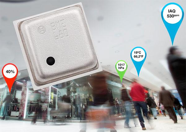
The BME680 from Bosch Sensortec is the world’s first environmental sensor combining pressure, humidity, temperature, and indoor air quality in a single 3×3mm2 package.

The new IC enables mobile devices and wearables to monitor indoor air quality measurement in a low power, small footprint package. The level of integration is what makes this solution so attractive as well as Bosch’s capabilities with software algorithms for a full solution.

Combo MEMS sensor solution with integrated gas sensor

The IC will enable multiple new capabilities for portable and mobile devices such as air quality measurement, personalized weather stations, indoor navigation, fitness monitoring, home automation, and other applications for the Internet of Things (IoT).

The gas sensor within the BME680 can detect a broad range of gases in order to measure indoor air quality for personal well-being, including Volatile Organic Compounds (VOC) from paints (such as formaldehyde), lacquers, paint strippers, cleaning supplies, furnishings, office equipment, glues, adhesives, and alcohol.


For more detail: Combo MEMS sensor solution with integrated gas sensor

Current Project / Post can also be found using:

  • Ch340 circuit

The post Combo MEMS sensor solution with integrated gas sensor appeared first on PIC Microcontroller.


Maxim bets its shirt on integration

$
0
0

Description

The MAX31865 is an easy-to-use resistance-to-digital converter optimized for platinum resistance temperature detectors (RTDs). An external resistor sets the sensitivity for the RTD being used and a precision delta-sigma ADC converts the ratio of the RTD resistance to the reference resistance into digital form. The MAX31865’s inputs are protected against overvoltage faults as large as ±50V. Programmable detection of RTD and cable open and short conditions is included.

Key Features

  • Simple Conversion of Platinum RTD Resistance to Digital Value
  • Handles 100Ω to 1kΩ (at 0°C) Platinum RTDs (PT100 to PT1000)
  • Compatible with 2-, 3-, and 4-wire Sensor Connections
  • Conversion Time: 21ms max
  • 15-Bit ADC Resolution; Nominal Temperature Resolution 0.03125°C (Varies Due to RTD Nonlinearity)
  • Total Accuracy Over All Operating Conditions: 0.5°C (0.05% of Full Scale) max
  • ±50V Input Protection
  • Fully Differential VREF Inputs
  • Fault Detection (Open RTD Element, RTD Shorted to Out-of-Range Voltage, or Short Across RTD Element)
  • SPI-Compatible Interface
  • 20-Pin TQFN Package

Maxim bets its shirt on integration

Maxim is staking its future on integrated analogue in the belief that sales of analogue SoCs will overtake discrete analogue sales within two years.

Asked by EW what integrated analogue means, Maxim responded: ‘Analogue has traditionally been divided into four discrete technologies –amplifiers, data conversion, interface and power management. Analogue integration combines these technologies into a single chip, which also includes microcontrollers and small amounts of memory in order to solve system-level problems in a single piece of silicon.’’

Pursuing its strategy of integrated analogue, Maxim has introduced five SoCs for factory automation and automotive applications.

One of the two factory automation products, the MAX78638, addresses 3-phase motor energy measurement and diagnostics. It contains a microcontroller, compute engine, ADC and flexible and configurable sensor interfaces that allow for the measurement of current, voltage, speed, vibration, position, and temperature. The ADC claims a less than 0.5% energy calculation error compared to the 5% of a standard microprocessor solution.

The other factory automation product, the MAX31865 is an RTD-to-digital converter, a single-chip claiming to lower cost by up to 50% and solve the common industrial design problem of digitising a platinum RTD (such as a Pt100 or Pt1000) resistance.


For more read: Maxim bets its shirt on integration

The post Maxim bets its shirt on integration appeared first on PIC Microcontroller.

Humidity sensor using 8051

$
0
0

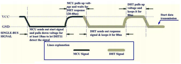
The communication protocol is explained as follows. The MCU (microcontroller unit) first sends a low signal of width 18mS to the DHT11. After this signal, the MCU pulls up the communication line and waits for the response from DHT11. It make take up to 2. to 40uS. Then the DHT11 pulls down the communication line and keeps it low for 80uS.

Humidity sensor using 8051

Then DHT11 pulls up the line and keeps it high for 80uS. Then the DHT pulls down the line for 50uS and the next high pulse will be the first bit of the data. The data is send in bursts of 8 bits. Each high pulse of the burst indicates a data signal. The 50uS low signals between the data bits are just spacers. The logic of the data bit is identified by measuring the width of it. A 26 to 28uS wide pulse indicates a “LOW” and 70uS wide pulse indicates a “HIGH”.  In simple words, an pulse narrower than 50uS can be taken as a “LOW”  and wider than 50us can be taken as a “HIGH”. The first 8 bits of the data burst represents the integral value of the relative humidity, second 8 bits represent the decimal value of the  relative humidity, third 8 bits represent the integral value of the temperature data, and the last 8 bits represent the decimal value of the temperature data, For DHT11 the decimal values are always zero and we are

For more detail: Humidity sensor using 8051

The post Humidity sensor using 8051 appeared first on PIC Microcontroller.

Acceleration sensor for infotainment systems

$
0
0
Overview
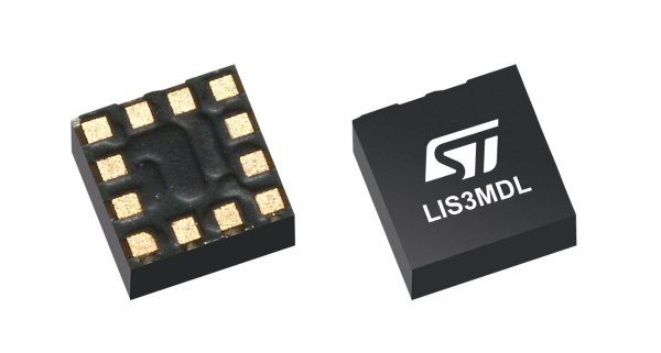
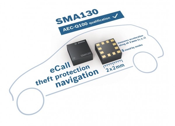
The SMA130
is a new compact
, triaxial acceleration
sen
sor for
non
safety automotive applications, packaged in a
LGA pac
k-
age. With its ultra
small footprint of only 2 mm x 2 mm and its
very low power consumption, it provides a cost
efficient one
Acceleration sensor for infotainment systems
chip
solution especially for infotainment
systems like in
dash navig
a-
tion or telematic on
board units.
The SMA130 detects accelera
tions in three perpendicular axes
and allows tilt, motion, vibration or shock sensing regardless of
the mounting orientation of the sensor. In particular the SMA130
eliminates the need for different sensor housings for slant
angle
correction in in
dash nav
igation systems.
Product description
The SMA
130 contains a digital 1
4
bit triaxial acceleration
sensor
with different measurement ranges between
±
2
g and
±
16
g.
Numerous programming options, a low signal noise and a very
small footprint make the SM
A
130 a highly versatile and easily
applicable
accelerometer.
For individual adjustments to the
a
p
plication, the user can easily choose via the digital interface
between four different measurement ranges and several low
pass filtering options. In addition, a
n 8
bit temperature signal is
available.
An embedded self
test ensures signal integrity.
The sensor accepts supply voltages between 1.62 V and
3.6 V
and can be operated in a temperature
range between
40 °C and +85
°C.
The sensor is RoHS compliant and
qualified
according to AEC
Q100.
The sensor features five
power
safe
modes
(current consum
p-
tion between 1 μA and 66 μA)
with fast wake up times below
2
ms
. The
se user
programmable modes
can be used for power
critical applications with
low signal samp
ling
rates.

The post Acceleration sensor for infotainment systems appeared first on PIC Microcontroller.
Sensor Technology for Health and Fitness Applications

$
0
0

By Jon Gabay

Contributed By Electronic Products

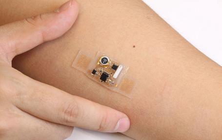
Determining the state of our health has always been a mattSensor Technology for Health and Fitness Applicationser of finding a way to monitor and measure the body’s most basic functions. Before instrumentation, visual indicators were used that allowed us to know, for example, what our body temperature should be, what a healthy pulse is, and what an acceptable respiration rate is.


Today, with an aging population more people now need some sort of portable health monitoring, which could take the form of devices that, among other things, dispense medication at regular intervals, stimulate the heart, or measure blood sugar levels and inject insulin. This article looks at medical- and fitness-sensor technology—contacted and contact-less, placed on the skin, subcutaneous, or internal—that now or soon will be available to design engineers. All parts, tools, and data referenced here can be found on the Digi-Key website.

Simple beginnings

The simplest form of a sensor is a transducer, which can be as basic as two different substances touching each other. The actual sensor element can be fabbed as a small discrete leaded component, or as part of a probe or electrode assembly. They can be as thin as a hair-like wire and can actually generate voltages themselves. Thermocouples are an example of voltage-generating sensor of dissimilar metals that creates voltages based on temperatures. Parts like the non-grounded Omron E52-CA15AYD32 4M, for example, measure temperatures using a K-type element with a 3.2 mm protective tube capable of skin mount or mounting in a stationary crevice.

Piezo effects can be taken advantage of to create energy from a tiny embeddable sensor when exposed to shock and vibration. A small, rather non-intrusive skeletal sensor could indicate too much physical trauma to a football player in real time to avert more serious injury. The miniaturizing of piezo sensors means they can now be weaved into textiles, bandages, or clothing. Sheet sensors like the TE Connectivity 2-1004347-0 are flexible, foldable, and can be cut to very specific states (Figure 1). A shoe insert for example, could determine if too much stress is being generated on downward steps to help diagnose back or joint issues.

For more detail:  Sensor Technology for Health and Fitness Applications

The post Sensor Technology for Health and Fitness Applications appeared first on PIC Microcontroller.

DC Motor Control using Temperature Sensor & 8051 Microcontroller

$
0
0

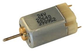
Microcontroller are widely used in electronics gadget and are one of the key element in developing any project and thus this project used 8051 microcontroller and will help in teaching about interfacing of temperature sensor with ATMEL microcontroller by means of ADC, to display the temperature on a 16×2 LCD and to rotate a DC motor at two different speeds at various temperatures. This project on digital thermometer is good implementation of project using microcontroller. DC Motor Control using Temperature Sensor & 8051 Microcontroller

In this project, we have now given a new temperature feedback to your temperature sensor which in turn modifications this to your similar a new analog voltage which is to be directed at a ADC. For you to convert this analog files in to a digital waveform, determined by a new reference voltage and that is fed to your microcontroller this temperature are going to be viewable with a 16×2 LCD. Control of DC motor is done in such a way that it runs on two different speed depending upon the temperature.
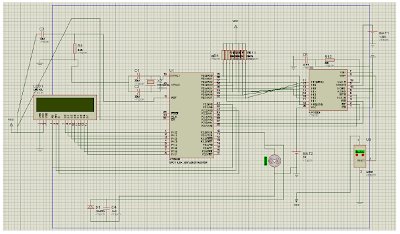
For implementation of this project Proteus software is used which is a software for microcontroller simulation, schematic capture and printed circuit board design and is developed by Labcenter electronics.DC Motor Control using Temperature Sensor & 8051 Microcontroller schematic

This project report contains the circuit diagram and its analysis along with the microcontroller programming for help. In this project LCD and ADC0804 interfacing with AtmelAT89C51 was studied and implemented on Proteus and same was assembled on a PCB. Thus we have successfully made a dc motor to run at different speeds by varying temperature. You can use this project for your reference and study work.


For more detail: DC Motor Control using Temperature Sensor & 8051 Microcontroller

Current Project / Post can also be found using:

  • motor pic
  • detector projects

The post DC Motor Control using Temperature Sensor & 8051 Microcontroller appeared first on PIC Microcontroller.

Viewing all 406 articles
Browse latest View live


<script src="https://jsc.adskeeper.com/r/s/rssing.com.1596347.js" async> </script>