Quantcast
Channel: sensor | Battery Guide
Viewing all 406 articles
Browse latest View live

ST shrinks MEMS gyro by 50% for smart clothes

$
0
0

The L3GD20H is a low-power three-axis angular rate sensor.

It includes a sensing element and an IC interface able to provide the measured angular rate to the external world through digital interface (I2C/SPI).

The sensing element is manufactured using a dedicated micromachining process developed by ST to produce inertial sensors and actuators on silicon wafers.

The IC interface is manufactured using a CMOS process that allows a high level of integration to design a dedicated circuit which is trimmed to better match the sensing element characteristics.

The L3GD20H has a full scale of ±245/±500/±2000 dps and is capable of measuring rates with a user selectable bandwidth.

The L3GD20H is available in a plastic land grid array (LGA) package and can operate within a temperature range from -40 °C to +85 °C.

Key Features

  • Wide supply voltage, 2.2 V to 3.6 V
  • Wide extended operating temperature range (from -40 °C to 85 °C)
  • Low voltage compatible IOs, 1.8 V
  • Low power consumption
  • Embedded power-down
  • Sleep mode
  • Fast turn-on and wake-up
  • Three selectable full scales up to 2000 dps
  • 16 bit rate value data output
  • 8 bit temperature data output
  • I2C/SPI digital output interface
  • 2 dedicated lines (1 interrupt, 1 data ready)
  • User enable integrated high-pass filters
  • Embedded temperature sensor
  • Embedded 32 levels of 16 bit data output FIFO
  • High shock survivability
  • ECOPACK® RoHS and “Green” compliant

ST shrinks MEMS gyro by

STMicroelectronics has recently introduced its smallest and lowest power chip-scale MEMS gyroscope for advanced motion-sensing applications.

The L3GD20H gyroscope measures 3x3mm and 1mm high, the device occupies little over half the volume of its predecessor.

One application is in so-called smart clothing which can be used in sports training aids, or medical therapy.

“Miniaturised, low-power sensors enable smart electronics to be used in items such as clothes or sports equipment, creating opportunities for exciting new products and services,” said Roberto De Nuccio, business development manager for ST’s motion MEMS division.

Other target applications are in prosthetics, medical instruments, goods tracking and power tools.

The gyroscope also draws 25% lower current than the previous generation of devices.

It has three selectable full-scale ranges (245/500/2000dps). Interfaces include I2C/SPI.

Internal low- and high-pass filters have user-selectable bandwidth and there is an on-chip temperature sensor and FIFO.

For more read: ST shrinks MEMS gyro by 50% for smart clothes

The post ST shrinks MEMS gyro by 50% for smart clothes appeared first on PIC Microcontroller.


Maxim bets its shirt on integration

$
0
0

Description

The MAX31865 is an easy-to-use resistance-to-digital converter optimized for platinum resistance temperature detectors (RTDs). An external resistor sets the sensitivity for the RTD being used and a precision delta-sigma ADC converts the ratio of the RTD resistance to the reference resistance into digital form. The MAX31865’s inputs are protected against overvoltage faults as large as ±50V. Programmable detection of RTD and cable open and short conditions is included.

Key Features

  • Simple Conversion of Platinum RTD Resistance to Digital Value
  • Handles 100Ω to 1kΩ (at 0°C) Platinum RTDs (PT100 to PT1000)
  • Compatible with 2-, 3-, and 4-wire Sensor Connections
  • Conversion Time: 21ms max
  • 15-Bit ADC Resolution; Nominal Temperature Resolution 0.03125°C (Varies Due to RTD Nonlinearity)
  • Total Accuracy Over All Operating Conditions: 0.5°C (0.05% of Full Scale) max
  • ±50V Input Protection
  • Fully Differential VREF Inputs
  • Fault Detection (Open RTD Element, RTD Shorted to Out-of-Range Voltage, or Short Across RTD Element)
  • SPI-Compatible Interface
  • 20-Pin TQFN Package

Maxim bets its shirt on integration

Maxim is staking its future on integrated analogue in the belief that sales of analogue SoCs will overtake discrete analogue sales within two years.

Asked by EW what integrated analogue means, Maxim responded: ‘Analogue has traditionally been divided into four discrete technologies –amplifiers, data conversion, interface and power management. Analogue integration combines these technologies into a single chip, which also includes microcontrollers and small amounts of memory in order to solve system-level problems in a single piece of silicon.’’

Pursuing its strategy of integrated analogue, Maxim has introduced five SoCs for factory automation and automotive applications.

One of the two factory automation products, the MAX78638, addresses 3-phase motor energy measurement and diagnostics. It contains a microcontroller, compute engine, ADC and flexible and configurable sensor interfaces that allow for the measurement of current, voltage, speed, vibration, position, and temperature. The ADC claims a less than 0.5% energy calculation error compared to the 5% of a standard microprocessor solution.

The other factory automation product, the MAX31865 is an RTD-to-digital converter, a single-chip claiming to lower cost by up to 50% and solve the common industrial design problem of digitising a platinum RTD (such as a Pt100 or Pt1000) resistance.


For more read: Maxim bets its shirt on integration

The post Maxim bets its shirt on integration appeared first on PIC Microcontroller.

Toshiba to sample 20Mpixel sensor

$
0
0

The Toshiba TCM5115CL is the latest addition to its sensor line-up for digital still cameras which offers high image quality using backside illumination technology (BSI) to improve sensitivity and imaging performance. The TCM5115CL is a 1/2.3-inch CMOS image sensor with an imaging pixel array of 5216 (H) × 3920 (V). Use of the CMOS process enables low power consumption and high-speed operations. The TCM5115CL is designed to meet the demands of high quality, fast frame rate image capture and HD video recording supporting smooth slow motion playback, and delivers the high frame rates 60 fps at 1080p and 100 fps at 720p.

Features
  •      1/2.3″ 20M resolution (1.2 µm)
  •       BSI
  •       I2C and SPI interface
  •        Sub-LVDS 12 lanes
  •        Binning:
  •        Horizontal 1/2
  •        Vertical 1/2 to 1/8
  •        Built-in Phase lock loop
  •         Defect pixel correction
  •         Picture flip (Horizontal and vertical)
  •          Global reset for mechanical shutter
  •          Strobe timing pulse


Toshiba to sample 20Mpixel sensor

In January, Toshiba is to sample a 20-megapixel (MP) CMOS image sensor, the TCM5115CL, for digital still cameras.


Volume production is scheduled for August.


The TCM5115CL offers the industry’s highest resolution in the 1/2.3 inch optical format, using backside illumination technology (BSI) to improve sensitivity and imaging performance.


Continued advances in the resolution offered by compact digital cameras—now in the range of 10- to 16MP—have brought with them the challenge of improving performance and picture quality with smaller pixels.


The TCM5115CL does just this by achieving a 15% improvement in full well capacity—the amount of charge an individual pixel can hold before saturating—against Toshiba’s previous generation 16MP sensor (pixel size = 1.34μm).


TCM5115CL delivers frame rates 60fps at 1080p and 100fps at 720p.


Toshiba’s Analog and Imaging System business is lookng for a 30% market share in CMOS imaging sensors in 2015.


For more read: Toshiba to sample 20Mpixel sensor


The post Toshiba to sample 20Mpixel sensor appeared first on PIC Microcontroller.

AMS uses 3D chip technology for smartphone sensors

$
0
0

Description

The AS3721 is a compact System PMU supporting up to 20 high current rails. The device offers advanced power management functions. All necessary ICs and peripherals in a battery powered mobilde device are supplied by the AS3721. It features 4 DCDC buck converters as well as 12 low noise LDOs. The different regulated supply voltages are programmable via the serial control interface. 3-4MHz operating with 1 uH coils is reducing cost and PCB space.

AS3721 further features 3 DCDC buck controller which are ideal to support processor currents ranging from 5A up to 20A. The multi-phase topology operating on 3MHz ensures fast load transient responses and reduces the footprint for external components.

The single supply voltage may vary from 2.7V to 5.5V.

Key Features

  • 4 DCDC step down regulators (3-4 MHz)
  • 3 DCDC step down controller
  • 12 universal LDOs
  • RTC
  • Supervisor with interrupt generation and selectable warning levels
  • General Purpose IOs
  • ADC with intern and external sources
  • OTP programmable Boot and Power-down sequence
  • Stand-by function with programmable sequence and voltages
  • Control Interface
  • Package:124-pin CTBGA (8x8mm), 0.5mm pitch

Applications

The device is suitable for Tablet PCs, NetBooks, portable media players, portable navigation devices, and mobile internet devices.

AMS uses 3D chip technology for smartphone sensors

Austrian chip maker ams is applying through-silicon via (TSV) 3D IC fabrication technology to its ambient light sensor devices.

TSV technology is being used to interconnect stacked wafers in FPGAs and memory chips and ams believes it can apply the technology to analogue sensors to very small wafer scale packages.

“We have been developing the TSV capability and expect to be in production with first sensors in the middle of the year,” said Thomas Riener, senior v-p marketing communications at ams.

The company is planning to develop more highly integrated and smaller ambient light sensors for use in smartphones and cameras.

After the acquisition of US-based light sensor firm TAOS in 2011, supplying sensors to smartphone manufacturers has become an important business for the Graz-based manufacturer.

“We have 40% market share in ambient light sensors in smartphones, “claimed Riener.

As a result the firm has doubled revenues in the last three years and sensor devices, standard products and Asics, make up 70% of sales for ams.

The mixed-signal company has also developed NFC and RFID “signal booster” devices for use in smartphones.

“These will be revenue driver this year and beyond, we already have a high number of design-ins,” said Riener.

The company also supplies an interface chip to MEMS microphone supplier Knowles. “

The company designs chip in the US and Europe, but all manufacturing is in Austria.

“Manufacturing is very important for us and we believe in retaining all critical production technologies,” said Riener.

“We believe analogue chip production is critical to Europe and the engineering talent is here,” said Riener.

Also important to ams is a new power management IC (PMIC) it originally designed as an Asic for Nvidia for its Tegra smartphone processor.


For more read: AMS uses 3D chip technology for smartphone sensors

The post AMS uses 3D chip technology for smartphone sensors appeared first on PIC Microcontroller.

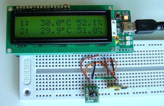
Interfacing DHT11 humidity and temperature sensor with PIC16F877A using pic microcontoller

$
0
0

After interfacing the DHT11 with Arduino uno board at the following post:
ARDUINO Humidity & Temperature Measurement Using DHT11 Sensor
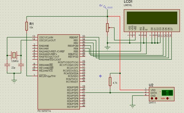
Now we are going to see how to interface this sensor with microchip pic16f877a.
There are some descriptions of how this sensor work  in the above link

A brief description of the code:
The code is written using MikroC compiler.
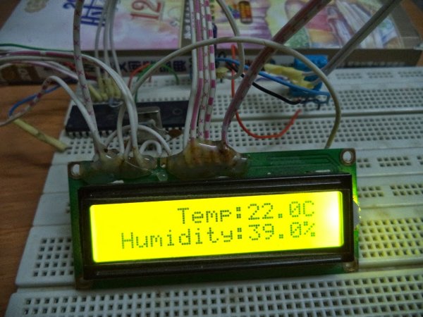
 First we must send a start signal to the sensor, we do that by configuring the pic pin connected to the sensor as output, the mcu sends 0 for 18ms then sends 1 for 30us.
After sending start signal to the sensor, the sensor will send a response signal to the mcu. To detect this signal mcu pin must be configured as input.
When the sensor finishes the response signal, it begins sending humidity and temperature data serially.
If there is a problem with the sensor or there is no sensor connected to the circuit, the LCD displays “there is no response from the sensor”. And if there is a problem in the sensor which means the values are incorrect the LCD displays “Check sum error”.
Interfacing DHT11 humidity and temperature sensor with PIC16F877A
// LCD module connections
 sbit LCD_RS at RB5_bit;
 sbit LCD_EN at RB4_bit;
 sbit LCD_D4 at RB3_bit;
 sbit LCD_D5 at RB2_bit;
 sbit LCD_D6 at RB1_bit;
 sbit LCD_D7 at RB0_bit;
 sbit LCD_RS_Direction at TRISB5_bit;
 sbit LCD_EN_Direction at TRISB4_bit;
 sbit LCD_D4_Direction at TRISB3_bit;
 sbit LCD_D5_Direction at TRISB2_bit;
 sbit LCD_D6_Direction at TRISB1_bit; 
 sbit LCD_D7_Direction at TRISB0_bit;
 // End LCD module connections
 char *text,mytext[4];
 unsigned char  a = 0, b = 0,i = 0,t1 = 0,t2 = 0,
               rh1 = 0,rh2 = 0,sum = 0;
 void StartSignal(){
 TRISD.F2 = 0;    //Configure RD2 as output
 PORTD.F2 = 0;    //RD2 sends 0 to the sensor
 delay_ms(18);
 PORTD.F2 = 1;    //RD2 sends 1 to the sensor
 delay_us(30);
 TRISD.F2 = 1;    //Configure RD2 as input
  }
 void CheckResponse(){
 a = 0;
 delay_us(40);
 if (PORTD.F2 == 0){
 delay_us(80);
 if (PORTD.F2 == 1)   a = 1;   delay_us(40);}
 }
 void ReadData(){
 for(b=0;b<8;b++){
 while(!PORTD.F2); //Wait until PORTD.F2 goes HIGH
 delay_us(30);
 if(PORTD.F2 == 0)    i&=~(1<<(7-b));  //Clear bit (7-b)
 else{i|= (1<<(7-b));               //Set bit (7-b)
 while(PORTD.F2);}  //Wait until PORTD.F2 goes LOW
 }
 }
 void main() {
 TRISB = 0;        //Configure PORTB as output
 PORTB = 0;        //Initial value of PORTB
 Lcd_Init();
 while(1){
 Lcd_Cmd(_LCD_CURSOR_OFF);        // cursor off
 Lcd_Cmd(_LCD_CLEAR);             // clear LCD
  StartSignal();
  CheckResponse();
  if(a == 1){
  ReadData();
  rh1 =i;
  ReadData();
  rh2 =i;
  ReadData();
  t1 =i;
  ReadData();
  t2 =i;
  ReadData();
  sum = i;
  if(sum == rh1+rh2+t1+t2){
  text = "Temp:  .0C";
  Lcd_Out(1,6,text);
  text = "Humidity:  .0%";
  Lcd_Out(2,2,text);
  ByteToStr(t1,mytext);
  Lcd_Out(1,11,Ltrim(mytext));
  ByteToStr(rh1,mytext);
  Lcd_Out(2,11,Ltrim(mytext));}
  else{
  Lcd_Cmd(_LCD_CURSOR_OFF);        // cursor off
  Lcd_Cmd(_LCD_CLEAR);             // clear LCD
  text = "Check sum error";
  Lcd_Out(1,1,text);}
  }
  else { 
  text="No response";
  Lcd_Out(1,3,text);
  text = "from the sensor";
  Lcd_Out(2,1,text);
  }
  delay_ms(2000);
  }
  }

Saturday, November 8, 2014

PIC16F877A LCD Example

This is just an example to show how to interface 16×2 lcd with pic16f877a. The lcd is going to display “PIC16F877A” in the the first line and “LCD Example” in the second line. The code is written using MikroC compiler.
// LCD module connections
sbit LCD_RS at RB5_bit;
sbit LCD_EN at RB4_bit;
sbit LCD_D4 at RB3_bit;
sbit LCD_D5 at RB2_bit;
sbit LCD_D6 at RB1_bit;
sbit LCD_D7 at RB0_bit;
sbit LCD_RS_Direction at TRISB5_bit;
sbit LCD_EN_Direction at TRISB4_bit;
sbit LCD_D4_Direction at TRISB3_bit;
sbit LCD_D5_Direction at TRISB2_bit;
sbit LCD_D6_Direction at TRISB1_bit;
sbit LCD_D7_Direction at TRISB0_bit;
// End LCD module connections
char *text;
void main() {
TRISB = 0;
PORTB = 0;
Lcd_Init();
Lcd_Cmd(_LCD_CURSOR_OFF);        // cursor off
Lcd_Cmd(_LCD_CLEAR);             // clear LCD
text = "PIC16F877A" ;
Lcd_Out(1,4,text);
text = "LCD Example";
Lcd_Out(2,4,text);
while(1);                     //infinite loop
}

Interfacing DHT11 humidity and temperature sensor with PIC16F877ATuesday, November 4, 2014

Real Time Clock

Now, I’m going to work with real time clocks, for that I will use the integrated circuit DS1307serial real time clock. I will use this ic with Arduino uno board and also I have to return to the pic microcontroller chip PIC16F877A. For the pic mcu I will use Microc and the full codes and schematics will be available on the next posts.
The DS1307 provides clock and calender. The clock shows seconds, minutes and hours and the calender shows day, month and year. The ds1307 uses I2C serial interface to transfer information with the microcontroller. More information in its datasheet.

Cd-Rom 3 phase Sensored BLDC Motor Arduino Controller

BLDC (brushless dc) motors are three phase dc motors, unlike the simple dc motors the bldc motors are more difficult to control. These motors are used in many applications for examples rc airplans and rc cars.
In this post we will see how to control cd-rom sensored BLDC motor using Arduino uno board. But first there are some things we should know in order to control the motor in easy way.
The bldc motor that we are going to use is sensored via hall effect sensors (position sensors) attached with the motor(3 sensors). Each sensor outputs digital high for 180 electrical degrees and low for the other 180 electrical degrees.these sensors are used to tell us where is the position of the motor, then when we know the position of the motor we will energize just tow windings (of three). The below figure shows how sensors outputs and the corresponding voltage applied to the motor:

The post Interfacing DHT11 humidity and temperature sensor with PIC16F877A using pic microcontoller appeared first on PIC Microcontroller.

Combo MEMS sensor solution with integrated gas sensor

$
0
0

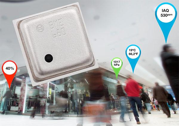
The BME680 from Bosch Sensortec is the world’s first environmental sensor combining pressure, humidity, temperature, and indoor air quality in a single 3×3mm2 package.

The new IC enables mobile devices and wearables to monitor indoor air quality measurement in a low power, small footprint package. The level of integration is what makes this solution so attractive as well as Bosch’s capabilities with software algorithms for a full solution.

Combo MEMS sensor solution with integrated gas sensor

The IC will enable multiple new capabilities for portable and mobile devices such as air quality measurement, personalized weather stations, indoor navigation, fitness monitoring, home automation, and other applications for the Internet of Things (IoT).

The gas sensor within the BME680 can detect a broad range of gases in order to measure indoor air quality for personal well-being, including Volatile Organic Compounds (VOC) from paints (such as formaldehyde), lacquers, paint strippers, cleaning supplies, furnishings, office equipment, glues, adhesives, and alcohol.


For more detail: Combo MEMS sensor solution with integrated gas sensor

The post Combo MEMS sensor solution with integrated gas sensor appeared first on PIC Microcontroller.

Digital Thermometer using PIC Microcontroller and LM35 Temperature Sensor

$
0
0

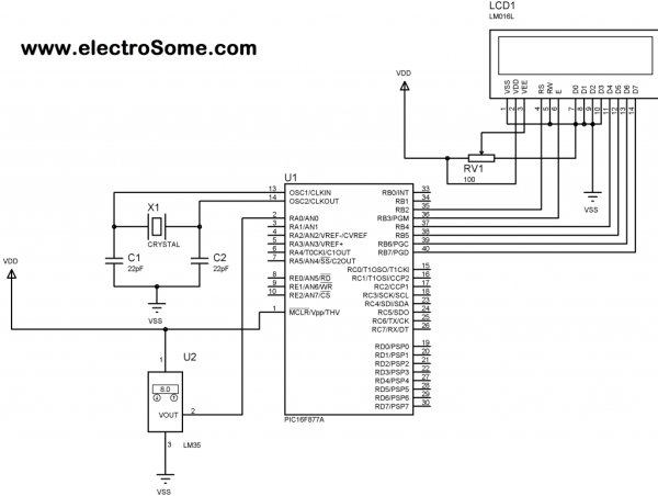
A Digital Thermometer can be easily constructed using a PIC Microcontroller and LM35 Temperature Sensor. LM35 series is a low cost and precision Integrated Circuit Temperature Sensor whose output voltage is proportional to Centigrade temperature scale. Thus LM35 has an advantage over other temperature sensors calibrated in Kelvin as the users don’t require subtraction of large constant voltage to obtain the required Centigrade temperature.

Digital Thermometer using PIC Microcontroller and LM35 Temperature SensorIt doesn’t requires any external calibration. It is produced by National Semiconductor and can operate over a -55 °C to 150 °C temperature range. Its output is linearly proportional to Centigrade Temperature Scale and it output changes by 10 mV per °C.

The LM35 Temperature Sensor has Zero offset voltage, which means that the Output = 0V,  at 0 °C. Thus for the maximum temperature value (150 °C), the maximum output voltage of the sensor would be 150 * 10 mV = 1.5V.  If we use the supply voltage (5V) as the Vref+ for Analog to Digital Conversion (ADC) the resolution will be poor as the input voltage will goes only up to 1.5V and the power supply voltage variations may affects ADC output. So it is better to use a stable low voltage above 1.5 as Vref+. We should supply Negative voltage instead of GND to LM35 for measuring negative Temperatures.

Digital Thermometer using PIC Microcontroller and LM35 Temperature SensorThis article only covers the basic working of Digital Thermometer using PIC Microcontroller and LM35, and uses 5V as Vref+. If you want more accurate results it is better to select Vref+ above 2.2V. I suggest you to use  MCP1525 IC manufactured by Microchip, which will provide precise output voltage 2.5.


For more detail: Digital Thermometer using PIC Microcontroller and LM35 Temperature Sensor

The post Digital Thermometer using PIC Microcontroller and LM35 Temperature Sensor appeared first on PIC Microcontroller.

Interfacing PIR sensor to 8051

$
0
0

PIR sensors are widely used in motion detecting devices. This article is about interfacing a PIR sensor to 8051 microcontroller. A practical intruder alarm system using PIR sensor and 8051 microcontroller is also included at the end of this article. Before going in to the core of the article, let’s have a look at the PIR sensor and its working.

PIR sensor.

PIR sensor is the abbreviation of Passive Infrared Sensor. It measures the amount of infrared energy radiated by objects in front of it. They does not  emit any kind of radiation but senses the infrared waves emitted or reflected by objects. The heart of a PIR sensor is a solid state sensor or an array of such sensors constructed from pyro-electric materials. Pyro-electric material is material by virtue of it generates energy when exposed to radiation.Gallium Nitride is the most common material used for constructing PIR sensors. Suitable lenses are mounted at the front of the sensor to focus the incoming radiation to the sensor face. When ever an object or a human passes across the sensor the intensity of the of the incoming radiation with respect to the background increases. As a result the energy generated by the sensor also increases. Suitable signal conditioning circuits convert the energy generated by the sensor to a suitable voltage output. In simple words the output of a PIR sensor module will be HIGH when there is motion in its field of view and the output will be LOW when there is no motion.

Interfacing PIR sensor to 8051DSN-FIR800 is the PIR sensor module used in this project.Its image  is shown above.  It operates from 4.5 to 5V supply and the stand by current is less than 60uA. The output voltage will be 3.3V when the motion is detected and 0V when there is no motion. The sensing angle cone is 110° and the sensing range is 7 meters. The default delay time is 5 seconds. There are two preset resistor on the sensor module. One is used for adjusting the delay time and the other is used for adjusting the sensitivity. Refer the datasheet of DSN-FIR800 for knowing more.

Interfacing PIR sensor to 8051.

The 8051 considers any voltage between 2 and 5V at its port pin as HIGH and any voltage between 0 to 0.8V as LOW. Since the output of the PIR sensor module has only two stages (HIGH (3.3V) and LOW (0V)) , it can be directly interfaced to the 8051 microcontroller.

The circuit shown above will read the status of the output of the PIR sensor and switch ON the LED when there is a motion detected and switch OFF the LED when there is no motion detected. Output pin of the PIR sensor is connected to Port 3.5 pin of the 8051. Resistor R1, capacitor C1 and push button switch S1 forms the reset circuit. Capacitors C3,C4 and crystal X1 are associated with the oscillator circuit. C2 is just a decoupling capacitor. LED is connected through Port  2.0 of the microcontroller. Transistor Q1 is used for switching the LED. R2 limits the base current of the transistor and R3 limits the current through the LED. Program for interfacing PIR sensor to 8051 is shown below.

Program.

PIR EQU P3.5
LED EQU P2.0
ORG 00H
CLR P2.0         
SETB P3.5
HERE:JNB PIR, HERE
     SETB LED
HERE1:JB PIR,HERE1
      CLR LED
SJMP HERE
END

The status of the output of the PIR sensor is checked using JNB and JB instructions. Code “HERE:JNB PIR, HERE” loops there until the output of the PIR sensor is HIGH. When it becomes HIGH it means a motion detected and the program sets P2.O HIGH in order to make the LED ON. The output pin of the PIR sensor remains HIGH for 5 seconds after a motion is detected. Code”HERE1:JB PIR,HERE1″ loops there until the output of the PIR sensor becomes LOW. When it becomes LOW the loop is exited and Port 2.0 is made LOW for switching OFF the LED. Then the program jumps back to label “HERE” and the entire cycle is repeated.


For more detail: Interfacing PIR sensor to 8051

Current Project / Post can also be found using:

  • interfacing pir sensor with 8051
  • pir sensor and 8051 interfacing
  • pirsensor interfacing with 8051 pdf

The post Interfacing PIR sensor to 8051 appeared first on PIC Microcontroller.


Acceleration sensor for infotainment systems

$
0
0
Overview
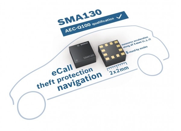
The SMA130
is a new compact
, triaxial acceleration
sen
sor for
non
-
safety automotive applications, packaged in a
LGA pac
k-
age. With its ultra
-
small footprint of only 2 mm x 2 mm and its
very low power consumption, it provides a cost
-
efficient one
Acceleration sensor for infotainment systems -
chip
solution especially for infotainment
systems like in
-
dash navig
a-
tion or telematic on
-
board units.
The SMA130 detects accelera
tions in three perpendicular axes
and allows tilt, motion, vibration or shock sensing regardless of
the mounting orientation of the sensor. In particular the SMA130
eliminates the need for different sensor housings for slant
-
angle
correction in in
-
dash nav
igation systems.
Product description
The SMA
130 contains a digital 1
4
-
bit triaxial acceleration
sensor
with different measurement ranges between
±
2
g and
±
16
g.
Numerous programming options, a low signal noise and a very
small footprint make the SM
A
130 a highly versatile and easily
applicable
accelerometer.
For individual adjustments to the
a
p
plication, the user can easily choose via the digital interface
between four different measurement ranges and several low
pass filtering options. In addition, a
n 8
-
bit temperature signal is
available.
An embedded self
-
test ensures signal integrity.
The sensor accepts supply voltages between 1.62 V and
3.6 V
and can be operated in a temperature
range between
-
40 °C and +85
°C.
The sensor is RoHS compliant and
qualified
according to AEC
-
Q100.
The sensor features five
power
-
safe
modes
(current consum
p-
tion between 1 μA and 66 μA)
with fast wake up times below
2
ms
. The
se user
-
programmable modes
can be used for power
-
critical applications with
low signal samp
ling
rates.

The post Acceleration sensor for infotainment systems appeared first on PIC Microcontroller.

LED fireflies prototype using PIC12f683 microcontroller

$
0
0

LED fireflies prototype

hello all, heres an attempt i made at something like an LED throwie..the problem (for me) with led throwies is that they just consume their battery, and produce light.. but they could be better at doing both..
LED fireflies

first you have to accept the premise that your willing to spend a bit more for the tradeoff..

the inspiration for this came from some of my other projects, and of course the “LED as a sensor” concept as well as the “LED throwie”

so the parts list:
1 common cathode, tri-color (RGB) LED
1 12f683 pic micro
1 coin cell battery holder

(cheap plug) http://www.makenyc.org/

Step 1: So whats it do?

the idea here is to use the led throwie/graffiti concept, to add a little life to my neighborhood that ive been missing for a long time now… fireflies..

the software is designed to use the LED as a light sensor (so as not to waste power during the day)

the led as an entropy source (to make each firefly unique moments after switching it on) to vary blink color, and rate.

and of course to play a flash pattern every so often in a way that seems “organic” and isnt just an “on/off” blink

and of course use as little power as possible!

(apologies for the darkness of the video, but the light had to be dim enough not to trip the fireflies daylight sensor)

For more detail: LED fireflies prototype using PIC12f683 microcontroller

The post LED fireflies prototype using PIC12f683 microcontroller appeared first on PIC Microcontroller.

Humidity and temperature measurements with Sensirion’s SHT1x/SHT7x sensors using PIC18F2550 (Part 1)

$
0
0

Temperature and relative humidity are two very important ambient parameters that are directly related to human comfort. Sometimes, you may be able to bear higher temperatures, if there is a lower relative humidity, such as in hot and dry desert-like environment. However, being in a humid place with not very high temperature may make you feel like melting. This is because if there is high relative humidity, sweat from our body will evaporate less into the air and we feel much hotter than the actual temperature. Humidifiers and dehumidifiers help to keep indoor humidity at a comfortable level. Today we will discuss about Sensirion’s SHT series of digital sensors, more specifically SHT11 and SHT75, which are capable of measuring both temperature and relative humidity and provide fully calibrated digital outputs. We will interface both the sensors to PIC18F2550 microcontroller and compare the two sets of  measurements to see the consistency between the two sensors. This tutorial is divided into two parts. The first part will cover all the details regarding the sensors, including their specification, interface, and communication protocol. The second part will be more focussed on the circuit diagram, implementation of the communication protocol with PICMicro, and the results.

Sensirion’s SHT1x

Theory

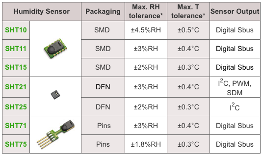
Sensirion offers multiple SHT series of digital sensors for measuring both relative humidity and temperature. The temperature is measured using a band-gap sensor, whereas the humidity sensor is capacitive; which means the presence of moisture in air changes the dielectric constant of the material in between the two plates of a parallel-plate capacitor, and hence varies the capacitance. The required signal conditioning, analog-to-digital conversion, and digital interface circuitries are all integrated onto the sensor chip. The various SHT series sensors have different levels of accuracy for humidity and temperature measurements, as described below.

SHT1x, 2x, and 7x series of humidity sensors (Source: http://www.sensirion.com)

SHT1x are available in surface mount type whereas SHT7x are supplied with four pins which allows easy connection. The SHT11 and SHT75 sensors both provide fully calibrated digital outputs that can be read through a two-wire (SDA for data and SCK for clock) serial interface which looks like I2C but actually it is not compatible with I2C. An external pull-up resistor is required to pull the signal high on the SDA line. However, the SCK line could be driven without any pull-up resistor. The signaling detail of the serial bus is described in the datasheet, which we will implement for PIC18F2550 microcontroller using mikroC pro for PIC compiler. The operating range of both the sensors is 0 to 100% for relative humidity, and -40.0 to 123.8 °C for temperature. The sensor consumes 3 mW power during measurement, and 5 μW, while in sleep mode.

The SHT11 module that I have got is from mikroElektronika. The sensor (SMD) is soldered on a tiny proto board with all the four pins accessible through a standard 0.1 inch spacing male header. The board comes with pull-up resistors connected to both SDA and SCK lines. One concern in this type of arrangement is the heat dissipated by the pull-up resistors could affect the measurements if the resistors and the sensor are close in the board. We will discuss about this issue later too. The SHT75 module from Sensirion, however, does not include any pull-up resistor for SDA line and therefore must be included externally.


For more detial: Humidity and temperature measurements with Sensirion’s SHT1x/SHT7x sensors using PIC18F2550 (Part 1)

The post Humidity and temperature measurements with Sensirion’s SHT1x/SHT7x sensors using PIC18F2550 (Part 1) appeared first on PIC Microcontroller.

Roll and Temperature sensor applications using PIC18F2550

$
0
0

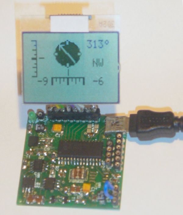
This page will show you how to use the TD-CMP modules in a way which fits you most.


Here are the technical specifications of the modules:

  • Compass: Resolution: 1° – Accuracy: 3°
  • Tilt/Roll: (TD-CMP02 and TD-CMP03 only) Resolution: 2° – Accuracy: 5°
  • Temperature: (TD-CMP03 only) Resolution= 1°C/F – Accuracy =1°
  • New: Sampling rate: 12,5 to 25 samples/second.
  • Easy Tilt/Roll calibration.(TD-CMP02 and TD-CMP03 only)
  • Interfaces: I²C, RS232 and mini-USB (as a HID device: PID=0461, VID= 1023)
  • Powered by USB bus or an external 5V.
  • Direct LCD readout possible. LCD contrast by user.
  • Low power LED lights when facing North (angle within 11,25° both left and right from North.)
  • USB Windows application (written in C#) available for free download.) Compatible with WinXp/Vista.
  • Source code (CCS C and C# .NET) and schematics (Eagle) can be purchased separately.
  • Module software is 100% upgradable with a simple bootloader.
  • PCB Dimensions: 40 x 41 mm or 1″57 x 1″61, weight: 10 grams.

Temperature sensor

These assembled modules are available from our online shop.

You may also purchase the bare pcb, a KIT DIY* version and the source code. KIT step-by-step construction guide.

New: compass calibration.

Schematics and pcb diagrams available for download. Last update: November 26, 2009.

DIY* = Do It Yourself

Power Source: JP4: Connect pin 2 to pin 3 to power the module directly from USB. Connect pin 1 to pin 2 when powered externally via JP3, pin 1.

New: Increase sampling speed from 12,5/second to 25/second: connect SPEED1 to SPEED2 (JP3, pin4 to JP3, pin2.)

LCD contrast Adjust: Connect pin 5, JP3 to +5V before powering up. Release when the desired the contrast is reached.


Tilt/Roll Calibration: (TD-CMP02 and TD-CMP03 only):

  • First place the module on a completely flat surface, power up.
  • Then shortly apply +5V (pin 1, JP2) to ADJUST (pin 5, JP3) Release after 1 second.
  • Check readings when applying tilt/roll to the module. Repeat the calibration procedure if necessary. Done.


Compass Calibration: (do not touch the PCB or chips whilst calibrating.)

  • First place the module on a completely flat surface, power up, head to North (position as shown in diagram and picture above), then turn the module slowly 360° (make 2-3 full clockwise and/or counter-clockwise spins.)
  • Now apply +5V (pin 1, JP2) to ADJUST (pin 5, JP3) Wait for 8-10 seconds; the LED will flash 3 times. Release the ADJUST pin from +5V. Power off and on.
  • Check compass readings when heading the module to N, S, E, W. Repeat the calibration procedure if necessary. Done.


Module RESET: apply GND to MCLR pin.


Temperature sensor: (TD-CMP03 only): The external LM335Z sensor connects to JP3 pin 4 and 6. No temperature will be displayed when the sensor is removed.


RS232 interface:

JP2 provides the interface to connect to your COM port and hyper terminal. Communications @ 115200 bpS, 8N1.

Use a level converter like the MAX3232 between the TD-CMP module and the pc serial port. See this example.

Also used for bootloading (module software update.) Check under the download section below for the latest version. Bootloading of the HEX-file can be done with Tiny Bootloader 1.91


For more detail: Roll and Temperature sensor applications using PIC18F2550

Current Project / Post can also be found using:

  • pic16f877a temperature projects

The post Roll and Temperature sensor applications using PIC18F2550 appeared first on PIC Microcontroller.

3D magnetic sensor from Infineon

$
0
0

Infineon will have engineering samples of a 3D magnetic sensor in July.

Called TLV493D-A1B6 performs magnetic field detection in x, y, and z direction allowing the sensor to measure 3D linear and rotation movements. The digital I²C interface enables bidirectional communication between sensor and microcontroller.3D magnetic sensor from InfineonThe sensor is for consumer and industrial applications that require 3D measurements or angular measurements or low power consumption, such as joysticks; control elements used for white goods and multi-function knobs; and electric meters where the 3D magnetic sensor helps to protect against tampering.

“Our TLV493D-A1B6 enables magnetic sensing to applications which have not been considered so far by making them smaller, more accurate and robust,” says Infineon’s Ralf Bornefeld, “our TLV493D-A1B6 marks the starting point for a new 3D magnetic sensor family. Later this year, we will offer a 3D sensor for automotive applications such as gear sticks and steering column controls.”

Today, up to three magnetic sensors – one for each dimension of external magnetic field – are needed to measure tampering attempts with large magnets. In future, the 3D magnetic sensor TLV493D-A1B6 replaces all three dimension sensors thus making e-meters smaller and more energy efficient.

The 3D sensor TLV493D-A1B6 detects all three dimensions of a magnetic field. Using lateral hall plates for the z direction and vertical Hall plates for the x and y direction of the magnetic field, the sensor can be used in a large magnetic field range of +/- 150mT (milli Tesla) for all three dimensions. This allows measuring and covering a long magnet movement. The large operation scale also makes the magnet circuit design easy, robust and flexible.

The TLV493D-A1B6 provides 12-bit data resolution for each measurement direction. This allows a high data resolution of 0.098mT per bit (LSB) so that even the smallest magnet movements can be measured.


For more detail: 3D magnetic sensor from Infineon

The post 3D magnetic sensor from Infineon appeared first on PIC Microcontroller.

Adds sensor nat Semi front end ICs

$
0
0

Description


The LMP90100/LMP90099/LMP90098/LMP90097 are highly integrated, multi-channel, low power 24-bit Sensor AFEs. The devices features a precision, 24-bit Sigma Delta Analog-to-Digital Converter (ADC) with a low-noise programmable gain amplifier and a fully differential high impedance analog input multiplexer. A true continuous background calibration feature allows calibration at all gains and output data rates without interrupting the signal path. The background calibration feature essentially eliminates gain and offset errors across temperature and time, providing measurement accuracy without sacrificing speed and power consumption.

Another feature of the LMP90100/LMP90099/LMP90098/LMP90097 is continuous background sensor diagnostics, allowing the detection of open and short circuit conditions and out-of-range signals, without requiring user intervention, resulting in enhanced system reliability.

Two sets of independent external reference voltage pins allow multiple ratiometric measurements. In addition, two matched programmable current sources are available in the LMP90100/LMP90098 to excite external sensors such as resistive temperature detectors and bridge sensors. Furthermore, seven GPIO pins are provided for interfacing to external LEDs and switches to simplify control across an isolation barrier.

Collectively, these features make the LMP90100/LMP90099/LMP90098/LMP90097 complete analog front-ends for low power, precision sensor applications such as temperature, pressure, strain gauge, and industrial process control. The LMP90100/LMP90099/LMP90098/LMP90097 are ensured over the extended temperature range of -40°C to +125°C and are available in a 28-pin HTSSOP package with an exposed pad.

Features

  • 24-Bit Low Power Sigma Delta ADC
  • True Continuous Background Calibration at all gains
  • In-Place System Calibration using Expected Value programming
  • Low-Noise programmable gain (1x – 128x)
  • Continuous background open/short and out of range sensor diagnostics
  • 8 output data rates (ODR) with single-cycle settling
  • 2 matched excitation current sources from 100 µA to 1000 µA (LMP90100/LMP90098)
  • 4-DIFF / 7-SE inputs (LMP90100/LMP90099)
  • 2-DIFF / 4-SE inputs (LMP90098/LMP90097)
  • 7 General Purpose Input/Output pins
  • Chopper-stabilized buffer for low offset
  • SPI 4/3-wire with CRC data link error detection
  • 50 Hz to 60 Hz line rejection at ODR ≤13.42 SPS
  • Independent gain and ODR selection per channel
  • Supported by Webench Sensor AFE Designer
  • Automatic Channel Sequencer

Nat Semi adds sensor front end ICs

Key Specifications

  • ENOB/NFR Up to 21.5/19 bits
  • Offset Error (typ) 8.4 nV
  • Gain Error (typ) 7 ppm
  • Total Noise < 10 µV-rms
  • Integral Non-Linearity (INL max) ±15 ppm of FSR
  • Output Data Rates (ODR) 1.6775 – 214.65 SPS
  • Analog Voltage, VA +2.85 to +5.5 V
  • Operating Temp Range -40°C to 125 °C
  • Package 28 Pin HTSSOP exposed pad

All trademarks are the property of their respective owners. TRI-STATE is a trademark of Texas Instruments.

National semiconductor has covered most analogue sensors by introducing two signal conditioning chips.

LMP90100 is for thermocouples, variable resistance, current loop and voltage sensors, and includes a 24bit ADC.

LPM91000 is for electrochemical sensors, for example gas detectors, and feeds an external ADC.

“Sensor-based system designs are time-consuming and complicated to develop, requiring an optimal design for each system,” said Anita Ganti, precision systems business director at National. “Until now, designers have developed customised analogue solutions that took weeks or even months to develop, but we can now help them get to market more quickly.”

The firm has coined the phrase ‘sensor AFEs‘ (analogue front ends) to describe the products, which are the first of a family, said Ganti.

Key to applying the devices is an on-line data base – currently holding 200 sensors – that can download appropriate setting parameter directly into associated development boards on the bench.


For more read: adds sensor Nat Semi front end ICs

The post Adds sensor nat Semi front end ICs appeared first on PIC Microcontroller.

Introducing Easy Pulse: A DIY photoplethysmographic sensor for measuring heart rate

$
0
0

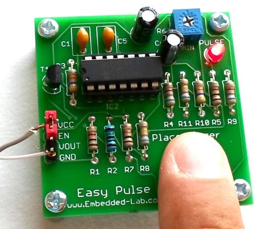
When I first built the Heart rate measurement through fingertip project, the infrared LED and photodiode used for finger photoplethysmography were actually from salvaged parts, and therefore, I could not provide specifications for them in the article. As a result of that it takes quite a bit of time to replicate that project with a different set of IR LED and photodiode as the values of the current limiting and biasing resistors may have to be changed for the new sensor to work properly. Today, I am going to talk about a revised version of the same project but with all the components specified this time. The new version uses the TCRT1000 reflective optical sensor for photoplethysmography. The use of TCRT100 simplifies the build process of the sensor part of the project as both the infrared light emitter diode and the detector are arranged side by side in a leaded package, thus blocking the surrounding ambient light, which could otherwise affect the sensor performance. I have also designed a printed circuit board for it, which carries both sensor and signal conditioning unit. I have named the board “Easy Pulse” and its output is a digital pulse which is synchronous with the heart beat. The output pulse can be fed to either an ADC channel or a digital input pin of a microcontroller for further processing and retrieving the heart rate in beats per minute (BPM).

Pulse Sensor

Theory

This project is based on the principle of photoplethysmography (PPG) which is a non-invasive method of measuring the variation in blood volume in tissues using a light source and a detector. Since the change in blood volume is synchronous to the heart beat, this technique can be used to calculate the heart rate. Transmittance and reflectance are two basic types of photoplethysmography. For the transmittance PPG, a light source is emitted in to the tissue and a light detector is placed in the opposite side of the tissue to measure the resultant light. Because of the limited penetration depth of the light through organ tissue, the transmittance PPG is applicable to a restricted body part, such as the finger or the ear lobe. However, in the reflectance PPG, the light source and the light detector are both placed on the same side of a body part. The light is emitted into the tissue and the reflected light is measured by the detector. As the light doesn’t have to penetrate the body, the reflectance PPG can be applied to any parts of human body. In either case, the detected light reflected from or transmitted through the body part will fluctuate according to the pulsatile blood flow caused by the beating of the heart.

The following picture shows a basic reflectance PPG probe to extract the pulse signal from the fingertip. A subject’s finger is illuminated by an infrared light-emitting diode. More or less light is absorbed, depending on the tissue blood volume. Consequently, the reflected light intensity varies with the pulsing of the blood with heart beat. A plot for this variation against time is referred to be a photoplethysmographic or PPG signal.

The PPG signal has two components, frequently referred to as AC and DC. The AC component is mainly caused by pulsatile changes in arterial blood volume, which is synchronous with the heart beat. So, the AC component can be used as a source of heart rate information. This AC component is superimposed onto a large DC component that relates to the tissues and to the average blood volume. The DC component must be removed to measure the AC waveform with a high signal-to-noise ratio. Since the useful AC signal is only a very small portion of the whole signal, an effective amplification circuit is also required to extract desired information from it.

Circuit diagram

The sensor used in this project is TCRT1000, which is a reflective optical sensor with both the infrared light emitter and phototransistor placed side by side and are enclosed inside a leaded package so that there is minimum effect of surrounding visible light. The circuit diagram below shows the external biasing circuit for the TCRT1000 sensor. Pulling the Enable pin high will turn the IR emitter LED on and activate the sensor. A fingertip placed over the sensor will act as a reflector of the incident light. The amount of light reflected back from the fingertip is monitored by the phototransistor.


For more detail: Introducing Easy Pulse: A DIY photoplethysmographic sensor for measuring heart rate

Current Project / Post can also be found using:

  • microcontroller based medical project
  • mini project of transducers
  • mini projects related to sensors and transduscer
  • sensor transducer and detector

The post Introducing Easy Pulse: A DIY photoplethysmographic sensor for measuring heart rate appeared first on PIC Microcontroller.


ADI moves MEMS gyro sensor to tactical grade

$
0
0

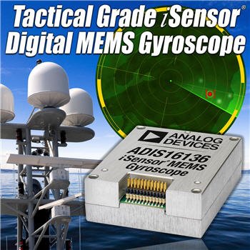
The ADIS16488 iSensor® MEMS IMU is a complete inertial system that includes a triaxis gyroscope, a triaxis accelerometer, triaxis magnetometer and pressure sensor. Each inertial sensor in the ADIS16488 combines industry-leading iMEMS® technology with signal conditioning that optimizes dynamic performance. The factory calibration characterizes each sensor for sensitivity, bias, alignment, and linear acceleration (gyroscope bias). As a result, each sensor has its own dynamic compensation formulas that provide accurate sensor measurements.

The ADIS16488 provides a simple, cost-effective method for integrating accurate, multiaxis inertial sensing into industrial systems, especially when compared with the complexity and investment associated with discrete designs. All necessary motion testing and calibration are part of the production process at the factory, greatly reducing system integration time. Tight orthogonal alignment simplifies inertial frame alignment in navigation systems. The SPI and register structure provide a simple interface for data collection and configuration control.

The ADIS16488 uses the same footprint and connector system as the ADIS16375, which greatly simplifies the upgrade process. It comes in a module that is approximately 47 mm × 44 mm × 14 mm and has a standard connector interface.

  • Triaxial, digital gyroscope with digital range scaling
    – ±450°/sec dynamic range
    – <0.05° orthogonal alignment
    – ~6°/hr in-run bias stability
    – 0.3°/√hr angular random walk
    – 0.01% nonlinearity
  • Triaxial, digital accelerometer, ±18 g
  • Triaxial, delta-angle and delta velocity outputs
  • Triaxial, digital magnetometer, ±2.5 gauss
  • Digital pressure sensor, 300 mbar to 1100 mbar
  • Fast start-up time, ~500 ms
  • Factory-calibrated sensitivity, bias, and axial alignment
    – Calibration temperature range: −40°C to +70°C
  • SPI-compatible serial interface
  • See datasheet for additional features

ADI moves MEMS gyro sensor to tactical grade

Analog Devices has introduced a new MEMS IMU (inertial measurement unit) in its iSensor range and the signficance is this is a tactical grade 10-degree-of-freedom (DoF) sensor.

“For industrial, military, and medical equipment designers who require the most accurate detection and control of motion in order to stabilize or navigate their applications, the ADIS16488 tactical grade IMU offers performance levels previously only available to those with unlimited budgets,” said Bob Scannell, iSensor business development manager, MEMS/Sensors technology group at Analog Devices.

The ADIS16488 integrates a tri-axis gyroscope, tri-axis accelerometer, tri-axis magnetometer and a pressure sensor into a single package.

“With equal or better performance to legacy high-end IMUs on key measures such as bias stability and angular random walk, the ADIS16488 provides better performance on the often more critical parameters of vibration-rectification, linearity, and bandwidth while consuming one-quarter the power, and at one-tenth the cost,” said Scannell.

The ADIS16488 iSensor 10-DoF MEMS IMU is a complete inertial measurement system that combines ADI’s high performance iMEMS® technology and sensor-signal processing expertise to optimize the IMU’s 10-DoF dynamic performance.

Operation is fully autonomous, including all embedded compensations, with valid data available from the SPI interface 500ms after applying power.

Calibration is carried out at the factory, and there is a Blackfin processor for configuring the interface for tuning embedded filtering and other diagnostics


For more read: ADI moves MEMS gyro sensor to tactical grade


The post ADI moves MEMS gyro sensor to tactical grade appeared first on PIC Microcontroller.

Infrared IR Sensor Interface with PIC18F4550 Microcontroller

$
0
0

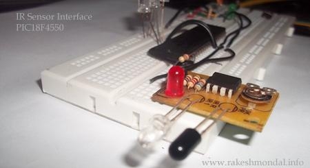
In my previous project we have made a simple IR sensor Circuit. In this project, as promised before – we are going to demonstrate a PIC18F4550 microcontroller interface to IR sensor circuit. We are just going to glow few on the pic18f4550 as an example, however you can do some more intelligent operations by adding some more logics to the microcontroller coding. Interfacing infrared Proximity sensors with Microcontroller is quiet easy.

Infrared IR Sensor Interface with PIC18F4550 Microcontroller This project is not only about interfacing an infrared IR sensor module but also we are going to learn – How to take digital input from a PIC18F4550 Microcontroller (Reading the Input with a Microcontroller). It means that the source code here will work same for taking input from a simple switch. You can replace the IR sensor with some simple PUSH Switch or some other types of proximity sensors . In case of push button you would need to pull down the pin to ground with 1 k resistance, however for IR sensor you won’t need to pull down the input pin with resistor.

Infrared IR Sensor Module

Let’s take a look at the IR Infrared Sensor Circuit Project module that we made in our previous project which is an inexpensive ( Low Cost ) sensor circuit module. You can find the schematic and PCB design in my previous post. There are three pins in the Schematic – Two pins for providing the input voltage and GND to the IR Sensor Module, and the third pin from the IR module is the IR control pin. This Control Pin from the IR sensor Module will be interfaced to the PIC18F4550 microcontroller for sensor input.

IR Sensor Module

Concept

The output from the IR sensor circuit will be connected to pins of a PIC18f4550 microcontroller and the microcontroller will regard it as digital input to read either 1 or 0.  According to the output from the IR sensor module, the PIC18F4550 will respond by glowing led. Since we just want to read some voltage in the microcontroller as input (either High or low) hence we are going to configure input pins as digital to read just 1 or 0 from the sensor.

PIC18F4550 Interface with IR sensor Circuit

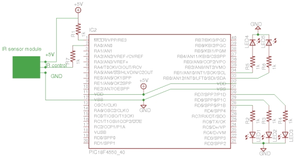
The output from the IR sensor circuit is connected to RA0 of the pic18f4550 which is configured as input with TRISB registers, and the output will be displayed on LED connected across RD7, RD6,RD5 (PORTD) and RB0 and RB1 (PORTB) which are configured as output pins. Follow the schematic below.

Schematic (IR sensor and PIC18F4550 microcontroller)

In this project we don’t need to perform any Analog to Digital Conversion(ADC), hence we are going to turn the ADC off (ADCON0bits.ADON = 0) and configure all the PINS to Digital.  At the default 1 MHZ oscillator frequency the output sometimes gives unstable result, hence tuning the microcontroller to 8MHZ solved the problem, Please note that pic18f4550 works by default on 1 MHZ and you can change the OSCCON bits settings to tune the oscillator frequency according to your requirement.

Infrared IR Sensor Interface with PIC18F4550 Microcontroller SchematicSearch in pic18f4550 datasheet for OSCCON register bits and you will find a nice description and bits settings table for available oscillator frequency and settings to configure the microcontroller oscillator frequency. Here I have configured the internal oscillator to 8MHZ to avoid switch debouncing. However it works well with 1MHZ settings as well. As a better plan the comparator is also turned off to avoid any conflict.

For more detail: Infrared IR Sensor Interface with PIC18F4550 Microcontroller

The post Infrared IR Sensor Interface with PIC18F4550 Microcontroller appeared first on PIC Microcontroller.

Chip senses gesture through electric fields

$
0
0

Description

The PS25401A is an ultra high impedance non-contact solid state electric potential sensor. It can be used to detect field disturbance due to the movement of a near-by object. This functionality can be employed in a range of applications including security motion sensors and non-contact electric switches for lighting, door opening, toys etc

The device uses active feedback techniques to both lower the effective input capacitance of the sensing element (Cin) and boost the input resistance (Rin). These techniques are used to realize a sensor with a frequency response suitable for remote sensing applications.

Also known as PS25401A EPIC Sensor.

Features

  • Ultra high effective input resistance, typically 20GΩ.
  • Effective input capacitance as low as 15pF.
  • Upper 3dB point typically 10kHz.
  • Operates with bipolar power supply from ±2.4V to ±4.0V.
  • Sensors supplied in a custom package with exposed pins for surface mount assembly

Chip senses gesture through electric fields

Plessey has released an electrostatic field sensing chip for security, switching and gaming applications.

It is the second member of the firm’s EPIC (electric potential IC) range, the first of which was a non-contact EEG (heart waveform) monitor.

“We have optimised the base layout of the EPIC sensor chip such that discrete movements of the human body can be detected with a range of up to several metres,” said Plessey CTO Dr Keith Strickland. “For example, the sensor can be configured to detect the proximity of a hand or to detect specific hand motions depending on the chip variant and the appropriate selection of circuit components external to the sensor.”

Called PS25401, the new chip can detect movement through walls, said Plessey, and can drive a relay “to act as a simple non-touch electric switch. It can also be used to replace, or as an adjunct to, a passive infra-red (PIR) sensor.”


For more read: Chip senses gesture through electric fields

The post Chip senses gesture through electric fields appeared first on PIC Microcontroller.

ST shrinks MEMS gyro by 50% for smart clothes

$
0
0

The L3GD20H is a low-power three-axis angular rate sensor.

It includes a sensing element and an IC interface able to provide the measured angular rate to the external world through digital interface (I2C/SPI).

The sensing element is manufactured using a dedicated micromachining process developed by ST to produce inertial sensors and actuators on silicon wafers.

The IC interface is manufactured using a CMOS process that allows a high level of integration to design a dedicated circuit which is trimmed to better match the sensing element characteristics.

The L3GD20H has a full scale of ±245/±500/±2000 dps and is capable of measuring rates with a user selectable bandwidth.

The L3GD20H is available in a plastic land grid array (LGA) package and can operate within a temperature range from -40 °C to +85 °C.

Key Features

  • Wide supply voltage, 2.2 V to 3.6 V
  • Wide extended operating temperature range (from -40 °C to 85 °C)
  • Low voltage compatible IOs, 1.8 V
  • Low power consumption
  • Embedded power-down
  • Sleep mode
  • Fast turn-on and wake-up
  • Three selectable full scales up to 2000 dps
  • 16 bit rate value data output
  • 8 bit temperature data output
  • I2C/SPI digital output interface
  • 2 dedicated lines (1 interrupt, 1 data ready)
  • User enable integrated high-pass filters
  • Embedded temperature sensor
  • Embedded 32 levels of 16 bit data output FIFO
  • High shock survivability
  • ECOPACK® RoHS and “Green” compliant

ST shrinks MEMS gyro by

STMicroelectronics has recently introduced its smallest and lowest power chip-scale MEMS gyroscope for advanced motion-sensing applications.

The L3GD20H gyroscope measures 3x3mm and 1mm high, the device occupies little over half the volume of its predecessor.

One application is in so-called smart clothing which can be used in sports training aids, or medical therapy.

“Miniaturised, low-power sensors enable smart electronics to be used in items such as clothes or sports equipment, creating opportunities for exciting new products and services,” said Roberto De Nuccio, business development manager for ST’s motion MEMS division.

Other target applications are in prosthetics, medical instruments, goods tracking and power tools.

The gyroscope also draws 25% lower current than the previous generation of devices.

It has three selectable full-scale ranges (245/500/2000dps). Interfaces include I2C/SPI.

Internal low- and high-pass filters have user-selectable bandwidth and there is an on-chip temperature sensor and FIFO.

For more read: ST shrinks MEMS gyro by 50% for smart clothes

The post ST shrinks MEMS gyro by 50% for smart clothes appeared first on PIC Microcontroller.

iProtoXi Aistin: Multi-Modular Sensor Platform

$
0
0

Internet of My Own Things

Intelligence without ambition is a bird without wings. –Salvador Dali
The Internet of Things has a different meaning for different people. For some, it means monitoring room temperatures from a mobile phone, whereas for other, it is controlling garden lighting from a laptop computer. For sports-minded people, it might mean logging their heart rate in real-time to a cloud service. Is there a common denominator between this wide range of different applications?

iProtoXi Aistin: Multi-Modular Sensor Platform

Our answer is Aistin. Instead of functionally limited ready-made IoT-sets, or flexible but unpractical self-wired desktop hassles, we wanted to inspire people to create new mobile products by providing the best that can be achieved with current technology:

  • Compactness – create tiny wrist worn devices instead of desktop monsters
  • Variability – uses a standard connector, enabling a large set of add-on boards
  • Truly mobile – run for a year and beyond with a small battery

In the heart of our Aistin product family is the very small Bus24 interface. Instead of making a proprietary solution of our own, we wanted to open this revolutionary technology to everyone. That is why the Aistin Bus24 is a free hardware standard with no license fees or other limitations. We really believe it will be included on all microcontroller boards in the future, and that the number of available add-on boards will increase exponentially.


For more detail: iProtoXi Aistin: Multi-Modular Sensor Platform

The post iProtoXi Aistin: Multi-Modular Sensor Platform appeared first on PIC Microcontroller.

Viewing all 406 articles
Browse latest View live


<script src="https://jsc.adskeeper.com/r/s/rssing.com.1596347.js" async> </script>