It follow a black line automatically and it also turn it direction according to black line. Liner follower robot is very famous project at university level among electrical, electronics, computer and software engineering students. There are a lot of competitions held every year in engineering universities related to robotics. But for first year engineering students, Liner follower robot is very popular.Because it is easy to make and can be easily ready to run with in minimum time.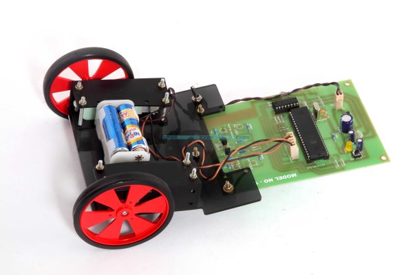
Applications of line follower robot
Line follower robot which is usually make at university level is just to make students familiar with the field of robotic. But actual robots use in fields are much more complex and they can perform very complicated task in industry. It is not possible to make a practical robot at university level. That’s why international robotics club encourage students to make simple robots like Liner follower robot, obstacle avoided robot, metal detection robot to get basic understanding of practical robots.In this article I have presented you an idea of Liner follower robot. How to make line follower robot using microcontroller.
Circuit working of line follower robot:
Block diagram of line follower using pic microcontroller is shown below. As I have clearly mentioned in block diagram. Two motors are used. One motor is attached with left Tyre of robot and another motor is attached with right Tyre of robot. Front wheel of Line follower robot is freely moving wheel. Motor driver IC is used to rotate both motors either clock wise or anti clock wise direction according to turning direction of Line follower robot. L298 motor driver IC is used as a motor driver IC. Microcontroller Atmega16 is used to give control signals to motor driver IC according to sensors output. Light dependent resistor in combunation with light emitting diode is used to sense black line. In case robot goes off from black line, respective sensor operate and microcontroller sense its value and take control control actions by turn motors either clock wise or anticlock wise.
Sensors circuit diagram for line follower robot
I have already mentioned sensors are used to sense black line. I have used seven sensors in this project. But you can also use 3 , 5 sensors according to width of black line. Light dependent resistor in combination with light emitting diode is used to sense either line follower robot is on black line or off line. Circuit diagram of single sensor is shown below. but you should connect all seven sensors on single strip with a distance of 2-3 cm between each set LDR and LED to get better results of line follower robot.
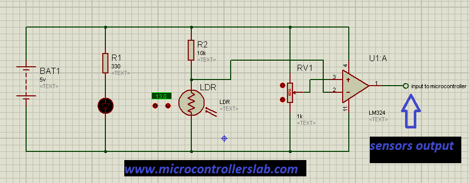
sensor for line follower robot
For more detail: Line follower robot using microcontroller
The post Line follower robot using microcontroller appeared first on PIC Microcontroller.