The are many cool sensors available now a days, ranging from IR distance sensor modules, accelerometers, humidity sensors, temperature sensors and many many more(gas sensors, alcohol sensor, motion sensors, touch screens). Many of these are analog in nature. That means they give a voltage output that varies directly (and linearly) with the sensed quantity. For example in LM35 temperature sensor, the output voltage is 10mV per degree centigrade. That means if output is 300mV then the temperature is 30 degrees. In this tutorial we will learn how to interface LM35 temperature sensor with PIC18F4520 microcontroller and display its output on the LCD module.
 First I recommend you to go and read the following tutorial as they are the base of this small project.
- Interfacing LCD Module with PIC Microcontrollers.
- Making the LCD Expansion Board for PIC18F4520.
- Using the ADC of PIC Microcontrollers.
After reading the ADC tutorial given above you will note the the PIC MCU’s ADC gives us the value between 0-1023 for input voltage of 0 to 5v provided it is configured exactly as in the above tutorial. So if the reading is 0 then input is 0v, if reading is 1023 then input is 5v. So in general form if the adc read out is val then voltage is.
unsigned int val;
val=ADCRead(0); //Read Channel 0
voltage= ((val)/1023.0)*5;
The above formula give voltage in Volts, to get Voltage in mili Volts (mV) we must multiply it with 1000, so
voltage=((val)/1023.0)*5*1000); //Voltage is in mV
since 10mV = 1 degree, to get temperature we must divide it by 10, so
t=((val)/1023.0)*5*100); //t is in degree centigrade
simplifying further we get
t=((val/1023.0)*500);
t=(val*0.48876);
we round off this value, so
t=round(val*0.48876);
remember round() is a standard c library function
![Interfacing LM35 Temperature Sensor with PIC Microcontroller schematic]() Hardware for LM35 based thermometer.
Hardware for LM35 based thermometer.
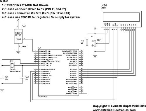
You will need a PIC18F4520 chip running at 20MHz attached with a standard 16×2 LCD Module and LM35 on AN0 pin. LM35 is a 3 pin device as show below.
connect the +Vs Pin to 5v and GND to GND. The output must be connected to the analog input pin 0 of the PIC18F4520 MCU. It is labeled AN0 in the datasheet. It is pin number 2 on the 40 pin package. It is also called RA0 because it is shared with PORTA0.
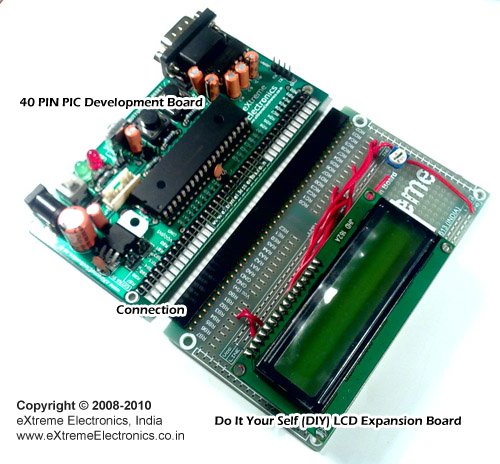
We will use our 40 PIN PIC Development board to realize the project. The base board has all the basic circuit to run the PIC. The extra part required for this project like LCD and the LM35 temperature sensor are installed in the expansion board.
For more detail: Interfacing LM35 Temperature Sensor with PIC Microcontroller.
Current Project / Post can also be found using:
- Circuit for fire fighting robot using pic mcro 16f887a
- transducer pic
- interfacing LM35 with pic microcontroller chip
- pic programming for robot
The post Interfacing LM35 Temperature Sensor with PIC Microcontroller. appeared first on PIC Microcontroller.